Powder bed fusion is an AM technique that uses either laser, thermal energy or electron beam to melt and fuse the material to form a 3D part
What is Powder Bed Fusion?
Powder bed fusion is one of seven Additive Manufacturing techniques, in which either laser, heat or electron beam is used to melt and fuse the material together to form a three-dimensional object.
Types of Powder bed fusion
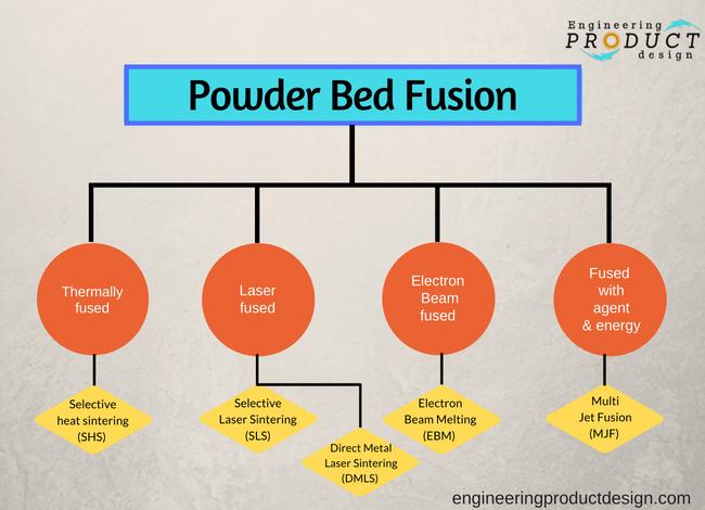
Both metal and plastic parts can be made using this technique and it can be classified into the following four groups by the energy source it uses to melt the material.
- Laser Fused
- Electron Beam fused
- Fused with agent and energy
- Thermally fused
Further, the Laser Fused technique can be subdivided into Selective Laser Sintering (SLS) where only plastic parts can be printed and Direct Metal Laser Sintering or it is sometimes called Selective Laser Melting (SLM) where, as the name suggests print metal. (figure 2)
EBM or Electron Beam Melting comes under Electron beam fused where metal powder is fused using electron beam under high vacuum.
HP’s Multi Jet Fusion (MJF) comes under the third category where the powder bed is heated uniformly at the start, where a fusing agent is used to bond the powder to create 3D geometrical parts.
Danish company Blueprinter’s Selective heat sintering (SHS) technology uses a thermal print head for sintering thermoplastic powder to create 3D parts which come under the fourth category, thermal powder bed fusion.
How powder bed fusion works
A schematic of a simple selective laser sintering process is shown in figure 3 below to help describe the powder bed fusion method.
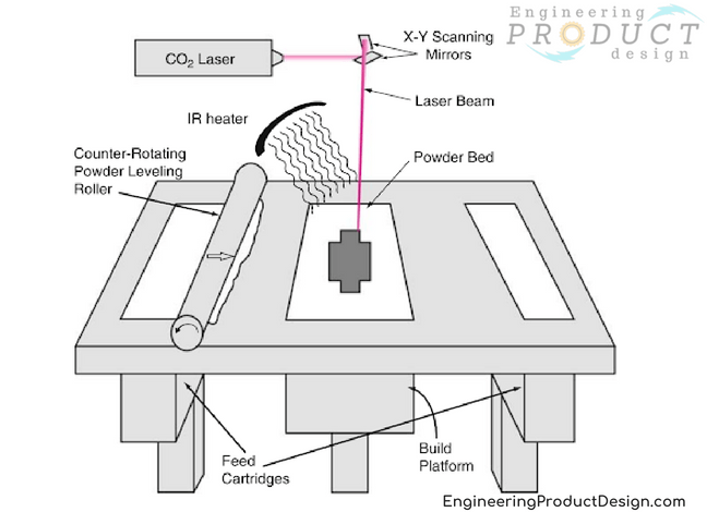
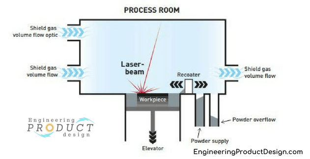
As shown in the above schematic, Powder bed fusion printers have two chambers, a Build chamber and a powder chamber along with a coating roller to move and spread the powder material across the build chamber. In some cases, the above setup is inside a partial vacuum chamber and filled with inert gas to protect the molten material from corroding. You can read why an inert atmosphere is preferred and why is it important?. Also, some manufacturers have two powder chambers on either side or the same side of the build chamber and use them as the excess overflow chamber as shown in figure 4.
Both powder and build chambers can move up and down on linear z-axis which is perpendicular to the top horizontal plane.
Although each type of powder bed fusion technique mentioned above varies with the different technology it uses to create the 3D parts, each broadly follows some common steps in the process to create the final part.
- 3D CAD models are converted into object cross-sections and saved as a .stl file. (Find out what’s a .stl file and other 3D printing acronyms & abbreviations)
- This stereolithographic file of the part or parts is loaded and placed in the correct orientation through the printer user interface. This could be desktop based or printer based software.
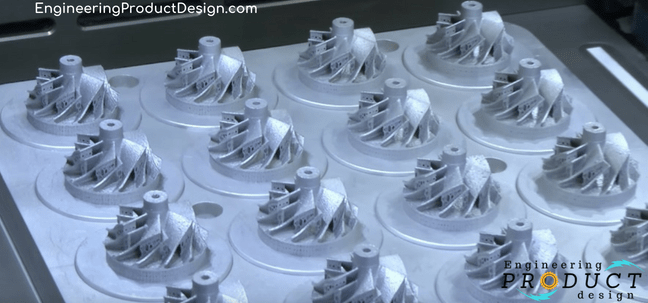
- As the image below shows, the build area can be filled with multiple parts to increase productivity.

- The powder chamber is filled with powdered build material (material in powder form) either manually or through an automated process. This could be via a build material cartridge or a hopper.
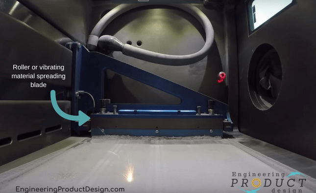
- The coating roller then deposits a thin layer of powder across the build platform. The resolution of the parts is defined by the thickness of the layer. Sometimes a scrapper or a blade or a levelling roller is used after the coating roller to ensure uniform thickness of the material top layer.

- Next, the energy source such as laser or electron beam is used to melt the deposited thin top layer of the metal powder selectively as per digital 2D cross-sectional data from the STL file.
- When that layer has been scanned and fused, the build platform is incrementally lowered down by the resolution of the bed z-axis. Simultaneously, the powder chamber is raised by the same amount. This defines the part resolution and dictates the thickness of the powder coating.
- The coating roller then deposits another thin layer of powder across the build chamber or platform on top of the fused section of a layer thickness.
- The energy source again scans and fuses the layer. This layering and fusing process continues until the 3D object is fully built.
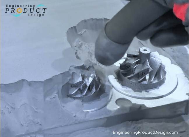
- At the end of the print operation, the part will be buried inside the powder build chamber. As shown below the powder will be removed leaving the fused part connected to the build plate. Although the powder bed fusion doesn’t need part support, the part still needs an anchor point to build from, hence the part will be built onto the built plate.
- Parts are then removed from the build plate by wire eroding or other machining means. Hence it’s crucial that the parts are designed and loaded in the correct most suitable orientation to avoid build errors and reduce waste and build time
- Depending on the size of the machine, the chambers can be either a separate replaceable cartridge or built-in hoppers.
Material suitability
The Powder bed fusion process can use any powder-based materials, but the following materials are the most common
- Selective heat sintering – Nylon (monochrome white thermoplastic powder)
- DMLS, SLS, SLM: Stainless Steel, Titanium, Aluminium alloy, Cobalt Chrome, Steel
- EBM: Stainless Steel, Titanium, Aluminium, Cobalt Chrome and copper
Advantages of powder bed fusion
- Low cost – Comparatively low cost. Manufacturing cost has come down in the recent past due to the price drop in powder bed fusion machines cost.
- No or minimum support – Mostly these do not need the use of support structures as the powder acts as an integrated support structure. But to get more accuracy sometimes the bottom build plate is used as the support.
- Wide material choice – A large range of materials including ceramics, glass, plastics, metals and alloys can be used to make 3D objects
- Powder recycling – Powder could be recycled in some cases although to getter better parts some time there is a need to preheat the powder which might make the powder stick together
Disadvantages of powder bed fusion
- Relatively slow and long print time – Powder preheating, vacuum generation, cooling-off period all add to the build time making it one of the slowest in the additive manufacturing
- Post-processing – Printed parts need.. to be post-processed before usage adding time and cost
- Weak structural properties – Structural properties of these aren’t good compared to other manufacturing processes due to layer-based manufacturing.
- Surface texture – Since the parts are made fusing metal powder together, surface quality depends on the grain size of the powder and would be very similar to manufacturing processes like sand casting, die casting etc
- Support build plate – Although technically it does not need supports, to avoid any issues such as warping due to residual stress support may have to be provided. Also, most of the printers use a build plate to build the parts .. hence needs post removal and post-processing. This can be reduced by designing with that in mind.
- Powder recycling – The powder is expensive but even more expensive is throwing out residual partially melted or unused powder. To speed up the print process, the powder is often preheated. This means that some powder is affected by the heat despite not being in the final part.
- Thermal distortion – Another problem, mainly for polymer parts, is thermal distortion. This can cause the shrinking and warping of fabricated parts.
- High power usage – Uses a lot of energy to create parts