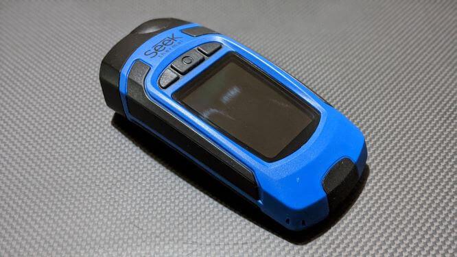
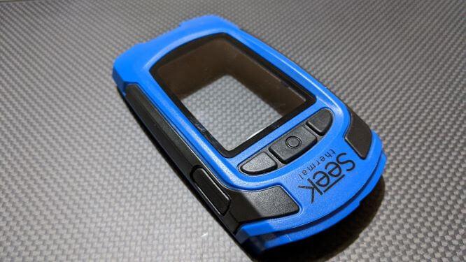
In our first product teardown and product design evaluation, we take apart a handheld thermal camera manufactured by SEEK thermal. It is a low to mid-range camera targeted towards general consumers, which combines a thermal sensor, a rechargeable battery and a colour display. The unit has three push buttons to control the displayed menu and a side button for the LED torch feature. It has a 206×156 thermal sensor and a 300-lumen LED light. A full technical specification can be found here.
This teardown is to understand the different mechanical design elements, electronic interface and manufacturing processes of some parts.
Rather than discussing every feature, we have grouped them into the following groups and concentrated on the hardware product design aspect of the camera.
- Product Architecture
- External housing
- Sealing
- External connector management
- Manufacturing process
Product Architecture
It is captivating how the design uses modular product architecture (Product architecture is one of three Embodiment design phases) instead of integral system-level design and the way it allocates specific functions to the modules.
- Thermal camera module
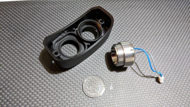
- LED light module
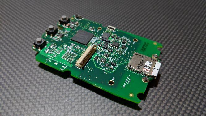
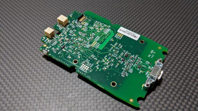
- Main controller – Printed circuit board
One of the main advantages of using a modular design is that the modules can be used in other designs within a family of products. In this camera, there are two thermal camera options (high and low resolution) which would mean that just the thermal camera module could be swapped to build a second variant. Modular design methodology works well if you have more than one product in your range.
External Housing
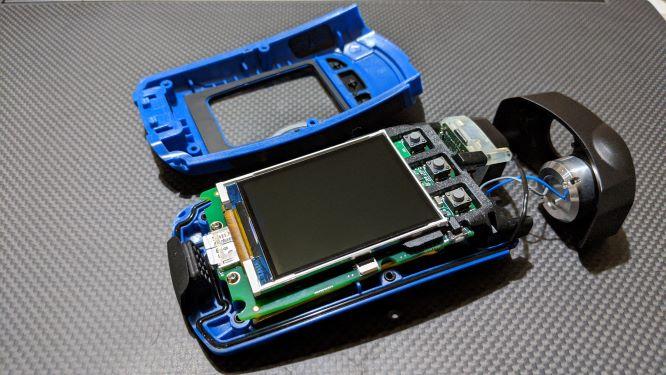
The unit has been split into three main external parts and an internal plastic frame. The top metal part houses both the thermal camera and the LED light, while the front and the rear plastic housing covers the main controller and the screen. Internally the main plastic frame holds the main PCB controller, Rechargeable battery and screen together in place.
The front and rear housing and frame are made of injection moulded plastic, while the top holder is CNC machined.
The front housing is held by four self-tapping screws, screwed into bosses in the rear housing, while the top metal housing is held by two self-tapping screws. Self-tapping screws are very common in plastic products, and careful consideration must be given to choosing the correct type depending on the material type and how much O-ring compression force is required to seal the housing.
The front plastic housing is manufactured using multiple materials (Clear acrylic material, main polymer and rubber for soft grips) using a technique called overmoulding (overmolding). Although this would have further added to the overall cost, by combining those parts the assembly cost of the camera has been reduced significantly.
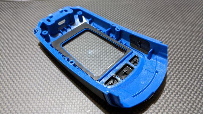
One of the key features of the design for assembly is the reduction in part count, especially during the assembly stages. This is done by combining the non-moving parts. The rear plastic housing is also manufactured using over moulding for hand grips. At the back of the housing, there are a couple of broached threaded inserts pushed in. The top CNC part is milled out of Aluminium alloy with looks like a black hard anodized surface finish.
Sealing
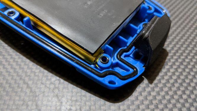
Three different parts make up the external housing which merges into one point, making sealing with a single O-ring impossible. Hence, a 3-dimensional O-ring has been used.
O-rings between the bosses of the housings are an interesting and uncommon way to seal the unit. Generally, fasteners are placed outside the main seal to ensure sealing. In contrast, these camera fasteners are inside the main O-ring seal, needing to be sealed individually. This goes against the concept of DFMA, where minimizing the part count is crucial.
Electronics Hardware management
The thermal camera, LED light, screen and battery had a single connection back to the main control board.
Our viewpoint
Positive design features
- Low-cost screen – A non-touch TFT screen and a menu system with comparatively cheaper push buttons for controls have been used saving the cost of an otherwise expensive touchscreen option
- As mentioned earlier, opting for a modular design enables the manufacture of a family of products cheaper. It also means that the modules can be replaced independently.
- By combining everything into a single controller board solution, the overall cost has been simplified and significantly reduced. Limiting the number of PCBs not only has reduced the manufacturing cost but also the test and assembly costs.
- USB connector – How the two screws have been used to secure the USB connector is preferred to rely on its soldering for strength.
- A single access port to access both the SD card and the USB connector makes the sealing of the port easier.
- The usage of a simple push-button is a more efficient and cost-effective method rather than using custom made tactile membrane keyboards which are very expensive and time-consuming to design
Negative design features
- During re-assembly plugging the FFCs from the thermal camera and the TFT screen were very difficult due to obscure access to the connectors.
- It was anticipated that the electronics, along with the thermal module, would have cost more. However, looking at the number of parts and the assembly process, it is evident that the assembly cost would have been the most. This isn’t a preferred outcome for a medium-size/quantity production batch.
- Broached push-in threaded inserts were used rather than flow inserts during the over moulding process
- The battery is accessible but heavily glued in place making replacement more difficult