Powder bed fusion is an AM technique that uses either laser, thermal energy or electron beam to melt and fuse the material to form a 3D part
Contents covered in this article
What is Powder Bed Fusion?
Powder bed fusion is one of seven Additive Manufacturing techniques, in which either laser, heat or electron beam is used to melt and fuse the material together to form a three-dimensional object.
Types of Powder bed fusion
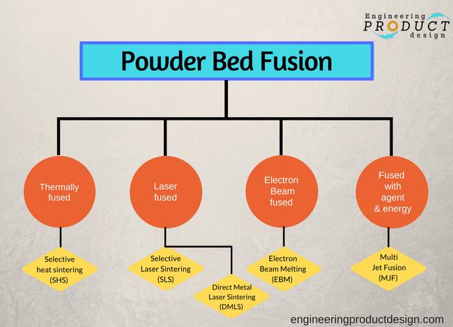
Both metal and plastic parts can be made using this technique and it can be classified into the following four groups by the energy source it uses to melt the material.
- Laser Fused
- Electron Beam fused
- Fused with agent and energy
- Thermally fused
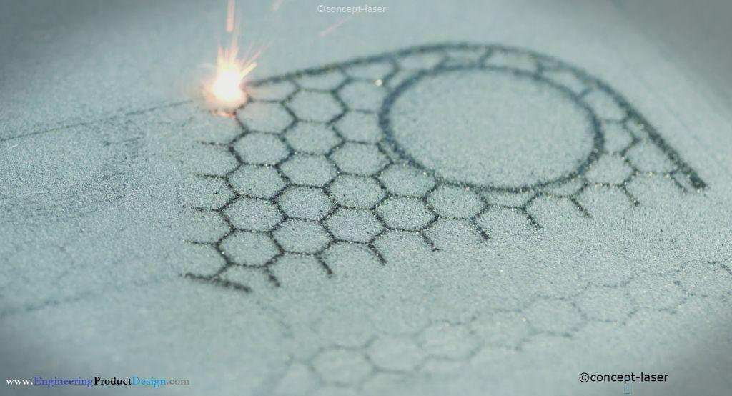
Further, the Laser Fused technique can be subdivided into Selective Laser Sintering (SLS) where only plastic parts can be printed and Direct Metal Laser Sintering or it is sometimes called Selective Laser Melting (SLM) where, as the name suggests print metal. (figure 2)
EBM or Electron Beam Melting comes under Electron beam fused where metal powder is fused using electron beam under high vacuum.
HP’s Multi Jet Fusion (MJF) comes under the third category where the powder bed is heated uniformly at the start, where a fusing agent is used to bond the powder to create 3D geometrical parts.
Danish company Blueprinter’s Selective heat sintering (SHS) technology uses a thermal print head for sintering thermoplastic powder to create 3D parts which come under the fourth category, thermal powder bed fusion.
How powder bed fusion works
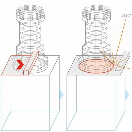
A schematic of a simple selective laser sintering process is shown in figure 3 below to help describe the powder bed fusion method.
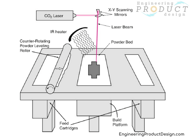
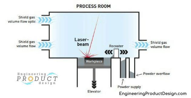
As shown in the above schematic, Powder bed fusion printers have two chambers, a Build chamber and a powder chamber along with a coating roller to move and spread the powder material across the build chamber. In some cases, the above setup is inside a partial vacuum chamber and filled with inert gas to protect the molten material from corroding. You can read why an inert atmosphere is preferred and why is it important?. Also, some manufacturers have two powder chambers on either side or the same side of the build chamber and use them as the excess overflow chamber as shown in figure 4.
Both powder and build chambers can move up and down on linear z-axis which is perpendicular to the top horizontal plane.
Although each type of powder bed fusion technique mentioned above varies with the different technology it uses to create the 3D parts, each broadly follows some common steps in the process to create the final part.
- 3D CAD models are converted into object cross-sections and saved as a .stl file.
- This stereolithographic file of the part or parts is loaded and placed in the correct orientation through the printer user interface. This could be desktop based or printer based software.
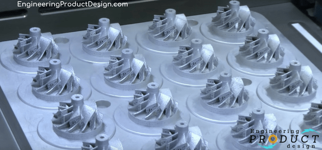
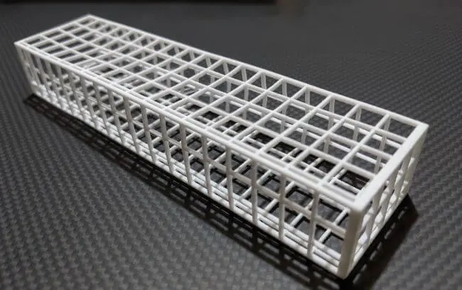
- As the image below shows, the build area can be filled with multiple parts to increase productivity.

- The powder chamber is filled with powdered build material (material in powder form) either manually or through an automated process. This could be via a build material cartridge or a hopper.
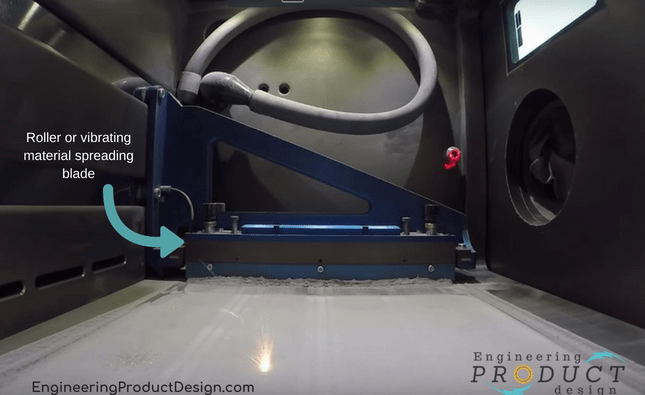
- The coating roller then deposits a thin layer of powder across the build platform. The resolution of the parts is defined by the thickness of the layer. Sometimes a scrapper or a blade or a levelling roller is used after the coating roller to ensure uniform thickness of the material top layer.

- Next, the energy source such as laser or electron beam is used to melt the deposited thin top layer of the metal powder selectively as per digital 2D cross-sectional data from the STL file.
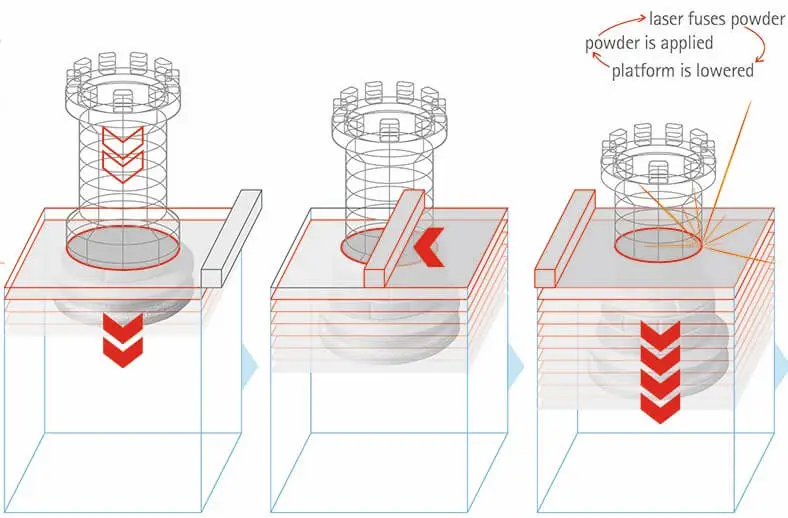
- When that layer has been scanned and fused, the build platform is incrementally lowered down by the resolution of the bed z-axis. Simultaneously, the powder chamber is raised by the same amount. This defines the part resolution and dictates the thickness of the powder coating.
- The coating roller then deposits another thin layer of powder across the build chamber or platform on top of the fused section of a layer thickness.
- The energy source again scans and fuses the layer. This layering and fusing process continues until the 3D object is fully built.
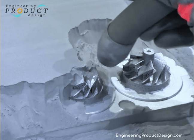
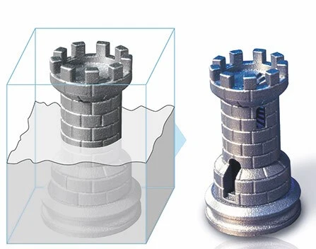
- At the end of the print operation, the part will be buried inside the powder build chamber. As shown below the powder will be removed leaving the fused part connected to the build plate. Although the powder bed fusion doesn’t need part support, the part still needs an anchor point to build from, hence the part will be built onto the built plate.
- Parts are then removed from the build plate by wire eroding or other machining means. Hence it’s crucial that the parts are designed and loaded in the correct most suitable orientation to avoid build errors and reduce waste and build time
- Depending on the size of the machine, the chambers can be either a separate replaceable cartridge or built-in hoppers.
Material suitability
The Powder bed fusion process can use any powder-based materials, but the following materials are the most common
- Selective heat sintering – Nylon (monochrome white thermoplastic powder)
- DMLS, SLS, SLM: Stainless Steel, Titanium, Aluminium alloy, Cobalt Chrome, Steel
- EBM: Stainless Steel, Titanium, Aluminium, Cobalt Chrome and copper
Advantages and Disadvantages of powder bed fusion
Advantages of powder bed fusion
- Low cost – Comparatively low cost. Manufacturing cost has come down in the recent past due to the price drop in powder bed fusion machines cost.
- No or minimum support – Mostly these do not need the use of support structures as the powder acts as an integrated support structure. But to get more accuracy sometimes the bottom build plate is used as the support.
- Wide material choice – A large range of materials including ceramics, glass, plastics, metals and alloys can be used to make 3D objects
- Powder recycling – Powder could be recycled in some cases although to getter better parts some time there is a need to preheat the powder which might make the powder stick together
Disadvantages of powder bed fusion
- Relatively slow and long print time – Powder preheating, vacuum generation, cooling-off period all add to the build time making it one of the slowest in the additive manufacturing
- Post-processing – Printed parts need.. to be post-processed before usage adding time and cost
- Weak structural properties – Structural properties of these aren’t good compared to other manufacturing processes due to layer-based manufacturing.
- Surface texture – Since the parts are made fusing metal powder together, surface quality depends on the grain size of the powder and would be very similar to manufacturing processes like sand casting, die casting etc
- Support build plate – Although technically it does not need supports, to avoid any issues such as warping due to residual stress support may have to be provided. Also, most of the printers use a build plate to build the parts .. hence needs post removal and post-processing. This can be reduced by designing with that in mind.
- Powder recycling – The powder is expensive but even more expensive is throwing out residual partially melted or unused powder. To speed up the print process, the powder is often preheated. This means that some powder is affected by the heat despite not being in the final part.
- Thermal distortion – Another problem, mainly for polymer parts, is thermal distortion. This can cause the shrinking and warping of fabricated parts.
- High power usage – Uses a lot of energy to create parts
Selective Heat Sintering (SHS)
Selective Heat Sintering (SHS) is an additive manufacturing (3D printing) technique that builds parts by selectively sintering powder materials using a thermal print head. Here’s an overview of the process, its advantages, and its applications:
Selective Laser Sintering (SLS)
Selective laser sintering uses a laser to melt and fuse fine polymer particles of material to create 3D objects.
What is Selective Laser Sintering?
Selective Laser Sintering (SLS) is a powder-based additive manufacturing technology that uses a laser to melt and fuse fine polymer particles of materials to create 3D objects. Commonly known as SLS, this 3D printing technology falls under the power bed fusion AM category. Powder bed fusion is one of the 7 types of Additive manufacturing technologies.
Selective laser sintering (SLS) 3D printing has become renowned for its low cost, comparably high production rate, ability to print complex geometries and increased choice of materials. Due to these characteristics, SLS 3D printing is ideal for rapid prototyping, functional prototype assemblies, pre-production parts and test rigs.
SLS also has the advantage of printing parts with thin walls and complex internal structures, making it a popular choice for various applications, including aerospace, automotive, and medical devices.
What are the characteristics of SLS?
| Tolerances & Accuracy | Typical tolerance – ± 0.3% of the dimension (Lower limit of ± 0.3 mm (± 0.012 in)) |
| Layer thickness | 0.050 – 0.120 mm It depends on the SLS printer’s quality |
| Minimum feature size | 0.5 mm or 0.8 mm The minimum feature size will depend on the type of features |
| Build volume | The average build volume is around 300mm x 300mm x 300mm. Larger industrial machines offer a 700mm x 380mm x 580mm build volume. |
How does Selective Laser Sintering work?
SLS Printer Overview
The schematic shows a typical SLS printer containing a build chamber, powder delivery chambers, spreading roller or arm, articulated laser beam, and heating systems.
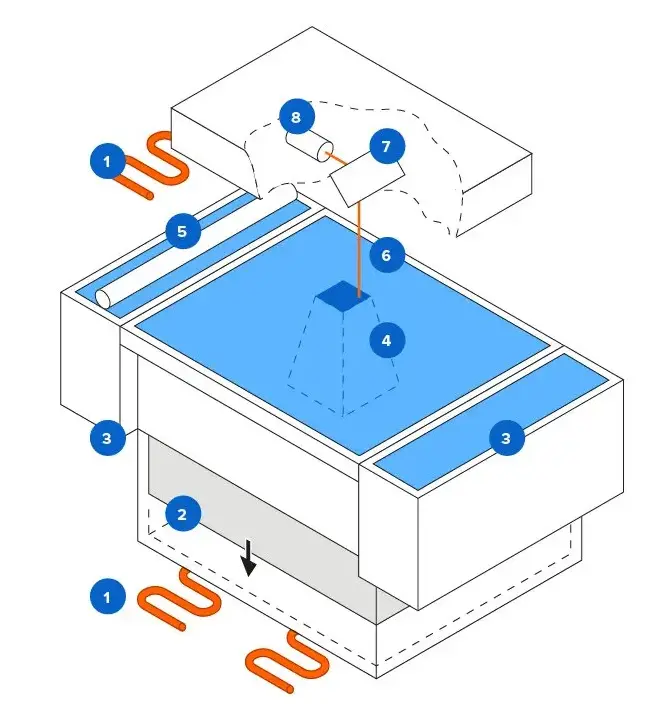
| ID No. | Description | ID No. | Description |
|---|---|---|---|
| 1 | Heaters | 5 | SLS powder recoater |
| 2 | SLS build chamber | 6 | Laser beam |
| 3 | Powder delivery chambers | 7 | X-Y scanning mirror |
| 4 | SLS printed part | 8 | Laser |
Selective laser sintering process steps
Selective laser sintering (SLS) is a 3D printing process that uses a laser to fuse fine material particles into solid structures selectively. The basic steps of the process are as follows:
- Powder bed preparation
- A fine, loose powder material, such as Nylon, is loaded into the powder delivery chambers and onto the build platform.
- The machine heats the powder inside the powder delivery chambers and builds a platform below the polymer melting temperature.
- The coating arm then spreads a thin layer of powder material evenly across the build platform.
- Laser scanning and fusing
- A laser beam is directed onto the surface of the powder bed, following the contours of the 3D model to fuse the particles selectively.
- The laser selectively sinters the material, causing it to stick together and form a solid structure. The fusing contour path comes from the digital 2D cross-sectional data from the STL file.
- Layer buildup
- After the first layer is complete, the machine lowers the build platform and spreads another layer of powder.
- The laser then scans this new layer, fusing the particles to form another solid layer. The printing process is repeated layer by layer until the entire object is built.
- Powder removal
- After the print, the platform is cooled, and the excess powder is removed, leaving behind the finished object.
- Post-processing
- Depending on the material used, the object may require additional post-processing steps, such as sanding or coating, to achieve the desired surface finish and durability.
Advantages and disadvantages of selective laser sintering
What are the advantages and disadvantages of selective laser sintering? Like any other manufacturing process, SLS has both benefits and limitations
Advantages of Selective Laser Sintering
Selective Laser Sintering (SLS) is a 3D printing technology with several advantages.
- No need for support structures – Unlike material extrusion printing technologies, SLS does not require support structures. The powder surrounding the built section supports the printed section. Hence, SLS is more cost-effective and efficient, producing parts with a cleaner finish without support.
- Powder recycling – Remaining unsintered SLS powder is collected and reused, reducing waste.
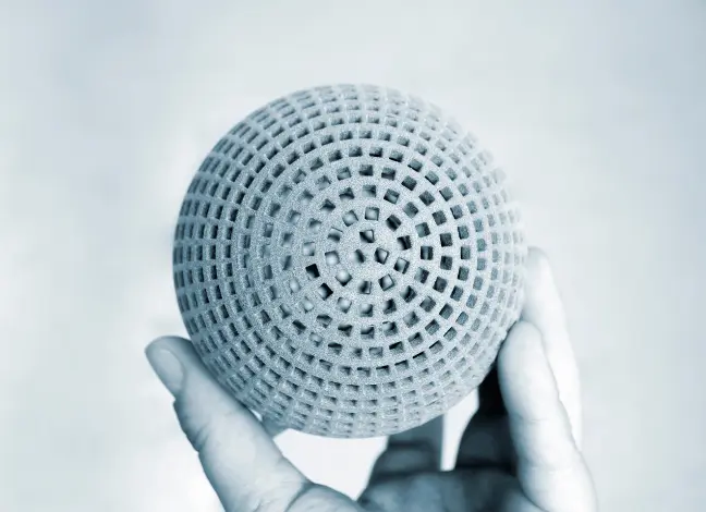
- Complex geometries – SLS can print complex and intricate parts with fine details, making it ideal for producing functional prototypes and end-use parts with complex geometries.
- Wide range of materials – SLS can use various materials, including Nylon, metal, and ceramics, providing designers and manufacturers with multiple application options.
- Good mechanical properties – SLS can produce strong and durable parts, making them suitable for high-stress and high-load applications in aerospace, automotive, and medical devices. In addition, unlike FDM, SLS provide isotropic mechanical properties.
- Large build envelope – Compared to SLA and FDM, SLS machines have larger build volumes, allowing for the production of more significant parts in a single print run.
- Fast production times – Since powders require little exposure to powerful lasers to fuse, SLS can print parts quicker than its counterparts. As a result, SLS production times are typically faster than other 3D printing technologies, making it ideal for short production runs and rapid prototyping.
- Dying and colouring – SLS parts have a porous surface finish, making them suitable for dyeing and colouring.
Overall, SLS is a versatile and highly efficient 3D printing technology that allows designers and manufacturers to produce complex, high-quality parts with various materials. Its advantages make it popular for applications from functional prototypes to end-use parts.
Disadvantages of SLS
Despite its many advantages, Selective Laser Sintering (SLS) also has some disadvantages, including:
- High equipment cost – SLS machines and materials can be expensive, making them a less accessible option for small businesses and individuals. This also drives the printing cost by service providers.
- Limited material options – SLS can only print Nylon based material.
- Low resolution – SLS resolution is lower than other manufacturing processes, making it unsuitable for producing highly detailed parts with fine features.
- Part warping – SLS parts can sometimes warp or deform due to the high heat generated during the printing process, which can affect the accuracy and dimensional stability of the finished part.
- Powder residue – SLS leaves a fine layer of unused powder on the part’s surface, which can be challenging to remove and affect the final product’s quality.
- Post-processing requirements – SLS parts may require additional post-processing steps, such as sanding or coating, to achieve the desired surface finish and durability.
While SLS offers many advantages, it is essential to consider these disadvantages and weigh them against your specific needs and requirements before choosing this technology for your 3D printing projects.
What materials are used for SLS
Selective Laser Sintering (SLS) is a 3D printing technology that can use a variety of materials, including:
| Material | Characteristics |
|---|---|
| PA12 – Polyamide 12 (Nylon) | PA12 mechanical properties are comparable to injection moulded polyamide, with high dimensional stability, wear and chemical resistance. |
| Polyether block amide (PEBA) | This thermoplastic polyamide elastomer (TPA) is a strong yet flexible rubber-like material. |
| Alumide (Aluminium-filled polyamide) | This aluminium-filled polyamide is characterised by high stiffness and good post-processing abilities. Metallic appearance |
| Carbon-fiber filled polyamide (PA-FR) | Excellent stiffness High weight-strength ratio Highly anisotropic |
| Glass-filled polyamide (PA-GF) | High stiffness Anisotropic behaviour Increased wear and temperature resistance |
| PA11 – Polyamide 11 (Nylon) | This environmentally friendly material is characterised by high-impact resistance and elongation at break. |
| TPE Thermoplastic elastomers | Tear and abrasion resistance Flexibility Durability |
| Polypropylene (PP) | Excellent plasticity High elongation Low moisture absorption High durability Excellent chemical resistance |
These materials offer a wide range of properties. As a result, they are suitable for various applications, but the choice of material will depend on the specific requirements and needs of the project. Therefore, it’s essential to consider the material’s strength, heat resistance, durability, cost, and availability when choosing a material for your SLS project.
Direct Metal Laser Sintering (DMLS)
Direct metal laser sintering is an AM technique that involves melting and fusing layers of metallic powder to create a 3D object.
What is Direct metal laser sintering?
Direct metal laser sintering (DMLS) is an additive manufacturing technique that involves melting and fusing layers of metallic powder using a computer-controlled, high-power laser beam.
DMLS is the leading additive method for making metal prototypes and falls under Powder Bed Fusion. It is similar to selective laser sintering of plastic resin but is suitable for use with metals including aluminium, stainless steel, titanium, cobalt chrome and Inconel. It offers good accuracy and detail and excellent mechanical properties.
DMLS can be used for very small parts and features, and because it is an additive process, it can reproduce geometries that might be impossible to machine, such as enclosed spaces. Layers can be as thin as 20 microns, and tolerances on small features can be as small as ±0.002 inches. Secondary operations on parts produced by DMLS can include machined drilling, slotting, milling and reaming, and finishing procedures, including anodising, electro-polishing, hand polishing, and powder coating or painting.
Hot isostatic pressing (HIP), solution annealing, and ageing are treatment processes that can enhance the mechanical properties of parts by relieving residual stress that develops during the sintering process.
Advantages and Disadvantages of Direct metal laser sintering
Advantages of DMLS
- Capable of working with nearly any alloy
- Mechanical properties parts equal to conventionally formed parts
- Can make geometries that are impossible to machine or cast
Disadvantages of DMLS
- Relatively slow
- Expensive
- Requires expertise to make quality parts
- Usually requires expensive post-processing
Electron Beam Melting (EBM)
In Electron beam melting, metal powder is melted and fused layer by layer using a high electron beam to create a 3D part.
What is Electron Beam Melting (EBM)?
Electron beam melting is one of the Powder bed fusion technologies, in which metal powder is melted and fused layer by layer using a high electron beam. Powder bed fusion is one of the 7 types of Additive manufacturing technologies.
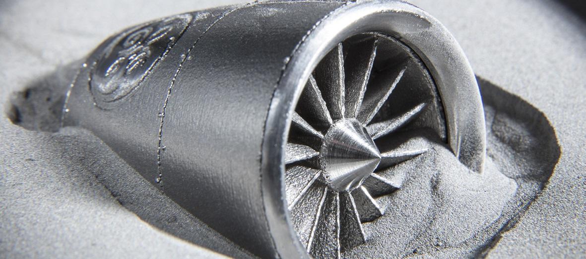
EBM is a proprietary additive manufacturing technology from Arcam, a GE Additive company. Watch the video to see the EBM procedure in action.
The EBM method employs a high-power electron beam that produces the energy needed for high melting capacity and productivity. The hot process produces components with minimal residual stress, and the vacuum maintains a clean and regulated atmosphere.
Characteristics of EBM
- Hot process – The electron beam heats each build layer throughout the hot process until the entire powder bed reaches an ideal process temperature unique to the material utilized. As a result, the EBM method yields components with no residual stresses and microstructures devoid of martensitic features.
- Vacuum chamber – The process takes place in a vacuum chamber to maintain a clean and regulated construction environment. Vacuum production is a key part of the EBM process since it keeps the build material’s chemical specifications.
- Sintering – Parts are generated free-floating in sintered powder during sintering. This makes pieces densely packed, reducing or eliminating mechanical support requirements.
Advantages and Disadvantages of Electron Beam Melting
Like any manufacturing process, EBM has its advantages and disadvantages.
Advantages of EBM
- Geometric freedom for engineering product designers
- Minimum material waste
- Less tooling and set-up costs
- Residual stress reduction due to increased process temperature
- Oxidation-reduction due to vacuum environment
Disadvantages of EBM
- Commercially available materials are limited
- A surface finish similar to sand casting
- Needs full understanding to get the full benefit of the process
How does the EBM work?
Refer to the 12 steps ” how Powder bed fusion works?”
Multi Jet Fusion (MJF)
Multi-jet Fusion (MJF) is an additive manufacturing technique invented by Hewlett-Packard that fuses powdered materials into a solid object using heat and a binding material.
What is Multi Jet Fusion (MJF)?
Multi jet fusion is a powder bed fusion technology involving a fine layer of powder spread over a build platform that the MJF printer fuses by selectively applying heat with a fusing and a detailing agent. Therefore, it is a multi-agent process of additive manufacturing.
This additive manufacturing technique produces functional parts with remarkable isotropy and quality. It is fast, and the cost per part is low. All these features make it ideal for applications such as:
- Automotive parts
- Protective equipment such as helmets
- Prosthetics
How does Multi jet fusion work?
Multi jet fusion printer Overview
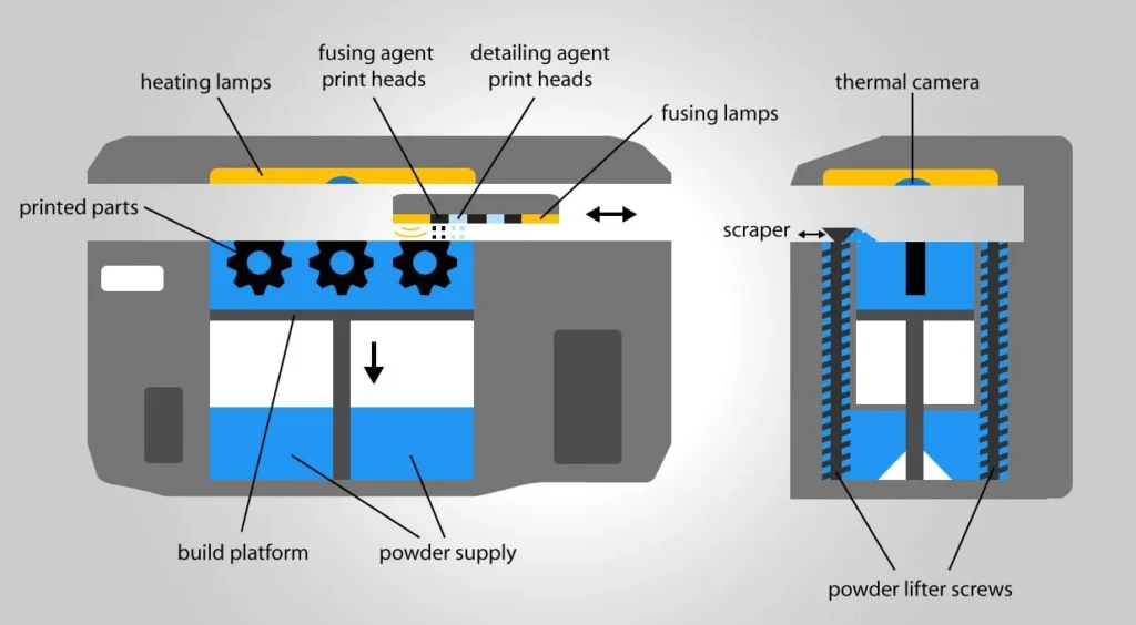
An MJF printer is usually composed of the following:
- A build chamber.
- A powder bed or build platform.
- A print head array. This array includes the fusing agent heads and the detailing agent heads. The print head also includes fusing lamps.
- An energy source. This source usually comes in the form of heating lamps.
- A cooling system.
- Control systems.
- Post-processing equipment that integrates a thermal camera, a scraper, and powder lifter screws to recover the unfused material.
It is essential to highlight that there are different models of MJF printers. So, the configuration may vary from one to another.
MJF process steps
As with any other additive manufacturing technology, creating a 3D model is the first step to building a prototype or fully functional piece with MJF. Then, it is necessary to load the model into the printer’s software, which creates the layers for the print. After that, the actual printing process begins by following these steps:
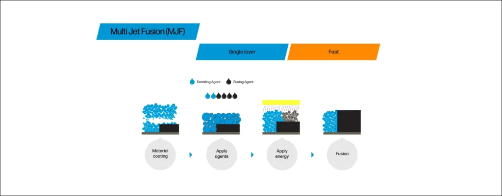
- A spreader applies a thin layer of powder to the work area. This layer is pre-heated until it reaches a temperature near the sintering temperature to prepare the material for fusing.
- Nozzles arranged in the printhead spray both the fusing and detailing agents on the build platform based on the data provided by the CAD software regarding the model.
- Heating lamps with infrared light move over the layer of powder. The multi-agent mixture absorbs the energy, thus generating the reactions between the agents and the material. As a result, the heat fuses the powder covered with the agents while leaving the rest of the material in the powder form. The detailing agent remains on the outer surface and edges of the layer to generate a better resolution and surface finish.
- The machine repeats the previous steps until the part is complete.
- Like the parts printed with SLS technologies, the post-processing of MJF parts involves time for cooling and cleaning to remove the unfused powder, usually with a vacuum system.
Advantages and disadvantages of MJF
Advantages of Multi jet fusion
- Low production times – Thanks to shorter cooling and post-processing times compared to similar technologies like SLS
- Outstanding mechanical properties – MJF machines print strong and functional parts. When testing for tensile strength under the ASTM D638 standard, MJF parts have reached up to 48 MPa. Also, it is possible to achieve low layer and wall thicknesses.
- High precision for fine details – MJF can jet material at 1200 DPI and offers tight tolerances of around +/- 0.012 in. (0.30mm).
- Highly reusable material – Regarding HP machines, the manufacturer claims that their machines can recover 80% to 85% of the unused powder for future reuse.
- No support structures required – A portion of the powder remains unfused. This powder acts as a support structure.
Disadvantages of Multi jet fusion
- Initial investment – MJF printers can be costly. So, MJF is a manufacturing process that requires a high initial investment. Material can also be expensive depending on the properties required. However, the reusability offered by the process usually offsets the cost of the material. The main problem is that HP MJF printers mainly use proprietary material. So, no competition might push prices lower.
- Geometry limitations – In general, MJF is capable of producing complex geometries. However, certain features are not possible, especially cured and hollow ones.
- Warping – Large parts and thin features are prone to suffer from warping.
What materials does MJF use?
Nylon is the preferred material for MJF manufacturing. However, it is not the only one. Here is a list of the materials used in MJF printing.
- PA 12 Nylon – Popular for its robustness, this thermoplastic boasts outstanding mechanical properties and chemical resistance. Suitable for functional parts.
- PA 12 Glass-filled Nylon – The glass-filled PA 12 is a version of the standard PA 12 but is more expensive. However, it offers higher rigidity and dimensional stability thanks to a glass bead reinforcement.
- PA 11 Nylon – Similar to PA 12 but more ductile. Suitable for functional parts.
- PP – This material is a polypropylene with high chemical resistance and low moisture absorption. The resulting parts can be welded and work well as functional parts.
- TPU01 Thermoplastic Polyurethane – This material is a type of elastomer offering an excellent combination of flexibility and shock absorption. Achieving high-resolution features is possible with this material.
- TPU M95A Thermoplastic Polyurethane – Another type of elastomer described by its manufacturers as a material with a high bouncing capacity and significant abrasion resistance.
- TPA Thermoplastic Polyamide – Also in the elastomer category, this lightweight material is an excellent choice for easy processing and flexible pieces due to its properties, such as a high elongation at low temperatures.
MJF vs SLS
MJF 3D printing is similar to SLS 3D printing, with both technologies achieving high-quality functional parts with smooth surface finishes.
Some of their similarities include:
- Additive Manufacturing (AM) category – MJF and SLS belong to PBF or Powder Bed Fusion, a class within additive manufacturing that includes all technologies using a heat source to build a part by solidifying a powder.
- Material and process – Since they belong to the PBF category, MJF and SLS use powder materials and fuse them thermally.
- Support structures – None of these additive manufacturing technologies require support structures since the powder bed serves this purpose.
- Surface finish – Both processes offer a rough and matte surface finish.
However, they have differences that are worth highlighting.
- Multi-agent process – MJF uses a fusing and a detailing agent that offers the opportunity to modify the part properties. On the other hand, SLS uses a laser to fuse the powder particles.
- Heat source – MJF uses infrared light as the heat source to fuse the material, while SLS uses a laser, usually a CO2 laser, as the heat source.
- Dimensional accuracy – Regarding dimensional accuracy, MJF and SLS are comparable. However, MJF offers slightly tighter tolerances at +/-0.2 mm for 100mm, while SLS works better at +/-0.3 mm for 100mm. Also, MJF achieves a print resolution of 80 microns with a minimum feature size of 0.5mm, while SLS reaches 100 microns and a minimum feature size of 0.75mm.
- Production speed – SLS requires more cooling and post-processing time. The faster post-processing is possible thanks to a dedicated station offered by HP.
- Materials – SLS offers more variety than MJF, although this may change in the future.
- Waste – SLS generates more waste than MJF. While SLS can only recover and reuse 30 to 50% of the powder, MJF can save up to 80% of the material that was not fused.
- Cost – MJF has the added cost of the binding material. However, the waste reduction provided by the material reusability offsets the added cost. Also, printing only one part is more expensive when using SLS, but the cost per part is comparable when scaling production.
Case Study: Advancing Automotive and Motorcycle Engineering with DMLS 3D Printing at BMW
At the forefront of automotive innovation, BMW has embraced the revolutionary potential of Direct Metal Laser Sintering (DMLS) in 3D printing. During its digital day in Mallorca, BMW unveiled the S1000RR sports bike chassis and a significant component for the i8 Roadster, both manufactured using DMLS.
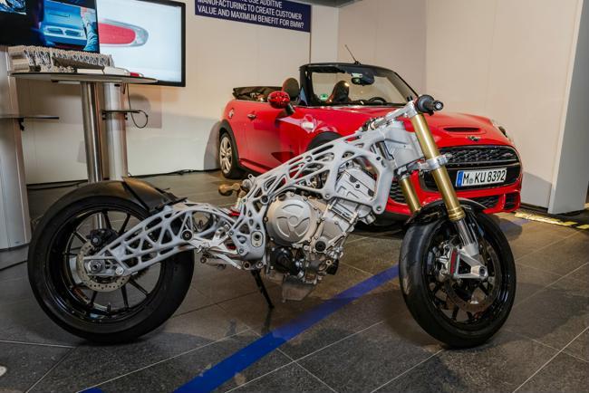
S1000RR Sports Bike Chassis:
BMW showcased the S1000RR sports bike chassis as a prime example of its 3D printing prowess. Although details on the chassis were limited, its futuristic design, characterised by free-flowing, organic curves, highlights DMLS’s capabilities in creating complex and aesthetically striking components.
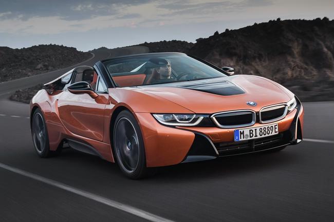
BMW i8 Roadster Aluminium Alloy Fixture:
BMW’s i8 Roadster also benefits from DMLS, particularly in producing a critical aluminium alloy fixture for the soft-top tonneau cover.
Bionic Geometry: The fixture’s geometry, optimised through topology optimisation, is designed to be lighter and stronger than traditional injection-molded parts. This is crucial for improving the vehicle’s performance while maintaining structural integrity.
Topology Optimization: This process refines the part geometry to reduce weight without compromising strength, taking full advantage of DMLS’s capabilities.
BMW’s use of DMLS to produce the S1000RR sports bike chassis and the i8 Roadster aluminium alloy fixture highlights the transformative impact of 3D printing in the automotive industry. By leveraging DMLS, BMW achieves unprecedented design freedom, weight reduction, and structural integrity, setting new benchmarks for performance and innovation in vehicle manufacturing. As BMW continues to explore the possibilities of DMLS, the technology promises to play a crucial role in the future of automotive engineering, paving the way for lighter, stronger, and more efficient vehicles.