Compression moulding is a conventional manufacturing process that uses heat and pressure to mould plastic resins and thermosets into a desired shape using a cavity tool.
Contents covered in this article
What is Compression moulding?
In Compression moulding, the material is placed directly inside a heated cavity and pressed into the desired shape using heat and high pressure. The material could be either powder, pre-shaped volume or liquid resin. Sometimes, manufacturers add filler materials to enhance the part and improve the process.

The process is primarily used with thermosetting plastics, although thermoplastics and elastomers are also used.
Compression moulding is well suited for creating parts with intricate features and high strength requirements. It is commonly used in automotive, aerospace, electrical and construction industries.
History of Compression Moulding
Compression moulding, a cornerstone in the evolution of plastics manufacturing, dates back to the early 20th century. Initially developed as one of the first techniques to shape plastics, it was primarily used to mould simple bakelite components, which were revolutionary at the time. As the process evolved, so did its applications and the materials used. In the 1950s, the introduction of thermosetting resins in automotive applications marked a significant milestone, allowing for the production of more durable and heat-resistant parts. By the 1970s, the integration of fibre-reinforced composites further expanded the capabilities of compression moulding, creating complex, high-strength, lighter and more efficient components. These advancements broadened its application scope across industries such as automotive, aerospace, and construction and laid the groundwork for modern composites. Compression moulding’s ability to adapt and incorporate new materials has ensured its continued relevance in contemporary manufacturing, where it remains a preferred method for producing large, intricate, and robust parts. This rich history underscores compression moulding’s pivotal role in improving plastics technology, demonstrating a legacy of innovation and adaptability.
Types of Compression moulding
There are several types of compression moulding, each suited to different applications:
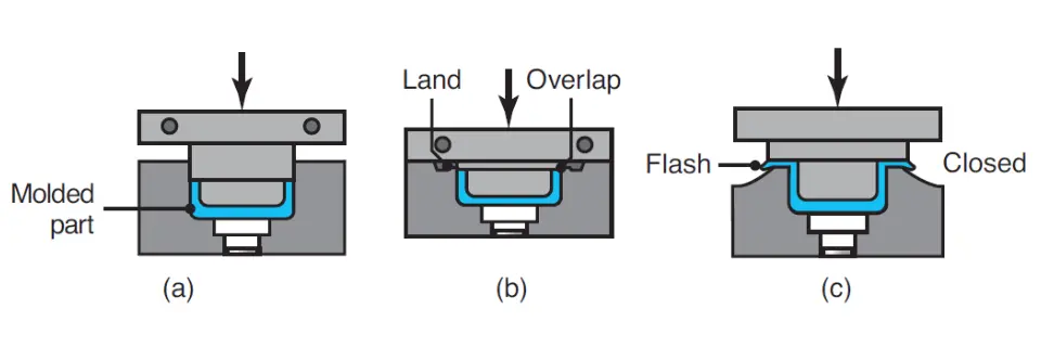
Flash Type
Flash-type compression moulding is used for shallow or flat components such as control panel dashboards and ashtrays. Excess material (flash) is squeezed out of the mould and later trimmed off.
Positive Type
This type of compression moulding is used for high-density parts. The mould cavity is filled precisely with the required material, minimising excess and waste.
Semi-Positive Type
The semi-positive type combines the advantages of the flash and positive types, making it versatile for a variety of parts.
How does Compression Moulding work?
The compression moulding process typically follows the following steps.
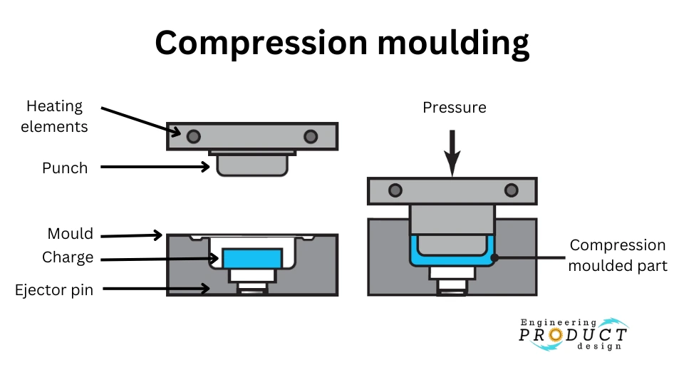
1. Material Preparation
Raw material, often in the form of pellets, granules, or sheets, is pre-heated to a material-specific temperature to soften it and make it malleable.
2. Mould Preparation
The mould is heated to the desired temperature to suit the material used. The mould cavity with the desired shape is lubricated to prevent the material from sticking.
3. Material Loading
The pre-heated material, called the “charge,” is placed inside the open mould cavity. This controlled amount ensures that the mould cavity is filled without excess.
4. Mould Closing
A simple mould consists of two halves, an upper and a lower, which close together like an injection moulding tool. Pressure is then applied to force the material to flow into the mould cavity. The combination of heat and pressure allows the material to flow and fill the mould cavity.
5. Curing and Setting
Pressure is maintained until the material cures or sets to take the mould cavity shape. The curing time varies depending on the material and also includes cooling time.
6. Mould Opening and Part Ejection
The mould is opened once the material is cured and the part is ejected.
Materials Used in Compression Moulding
Compression moulding accommodates various materials:
- Thermosetting Plastics – Silicone, phenolics, and melamine are common known for their strength and durability.
- Thermoplastics – These can be used but are less common due to different processing needs.
- Elastomers: – Used when flexibility and resilience are required.
Specialty Materials:
- Carbon-fiber Reinforced Plastics (CFRP) – Used for high-strength, lightweight components.
- Glass-filled Plastics – Provide added strength and rigidity.
- Liquid Silicone Rubber (LSR) – Offers excellent flexibility and is used in medical and consumer products.
key properties:
| Material | Key Properties |
| Phenolic Resins | High heat resistance Excellent electrical insulation Good dimensional stability High strength and rigidity |
| Melamine Resins | Heat resistance Hardness and durability Good surface finish Resistant to chemicals and staining |
| Epoxy Resins | Strong adhesion High mechanical strength Excellent chemical resistance Good electrical properties |
| Polyester Resins | High strength-to-weight ratio Corrosion resistance Good thermal stability Transparent to translucent |
| Silicone Rubbers | High-temperature resistance Flexibility and elasticity Excellent chemical resistance Good electrical insulation |
| Bakelite | Heat resistance High mechanical strength Good electrical insulation Hard and brittle |
| Polyurethane | High abrasion resistance Good tear strength Flexible to rigid Good oil and solvent resistance |
| Thermoplastic Elastomers | Flexible and elastic Can be moulded and remoulded Good chemical resistance Low-temperature flexibility |
| Carbon Fiber Composites | High strength Lightweight High stiffness Excellent fatigue resistance |
| Glass Fiber Composites | High tensile strength Good thermal insulation Corrosion resistance Economical |
| Polyimide | High thermal stability Good mechanical strength Low creep Excellent chemical resistance |
| Polycarbonate | High impact resistance Transparent Good thermal resistance Tough and durable |
| Polyethylene (HDPE) | High impact resistance Chemical resistance Good low-temperature properties Lightweight |
| Polypropylene | Chemical resistance Good fatigue resistance High melting point Tough and flexible |
Advantages & disadvantages of compression moulding
Advantages
- Lower Tooling Cost – Compression moulding uses simpler and less expensive moulds than injection moulding.
- Cost-Effective – With its low tooling cost, the process can be cheaper than injection moulding and plastic extrusion.
- Suitable for Large Parts—Compression moulding is well-suited for producing large parts like car bumpers. Depending on the design, compression moulding can be vastly cheaper for substantial parts than injection moulding.
Disadvantages
- Slow Cycle Time – The compression cycle time is longer than in manufacturing processes like injection moulding, leading to a lower production rate.
- Material Waste – Compression moulding can produce more material waste depending on the part design and the type of mould used.
- Limited Automation Possibility – Implementing automation in compression moulding is challenging, making it labour-intensive.
As a product designer, you must work closely with the manufacturer from an early stage to improve the design for material flow and part geometry.
Applications of Compression Moulding
Compression moulding is used in various industries due to its versatility and cost-effectiveness. Some common applications include:
Automotive Industry – Compression moulding produces components like car bumpers, dashboards, and under-hood parts due to its ability to create large and durable parts.
Aerospace Industry—Compression moulding is used in the aerospace industry to make high-strength and lightweight parts, such as interior panels and structural components.
Electrical Industry – Electrical components, such as insulators and switchgear, are often produced using compression moulding because of its precision and reliability.
Construction Industry – The construction industry uses compression moulding to produce items like roofing tiles and insulation panels, which require durability and precise dimensions.
Design for Manufacturing (DFM) Guidelines for Compression Moulding
To optimise the compression moulding process, designers should follow these guidelines:
Material Selection – Choose a material suitable for the process, generally thermosetting plastics like silicone, phenolics, and melamine.
Surface Finish — Select an appropriate surface finish. Avoid specifying a highly polished finish, as it adds cost.
Avoid Undercuts—Avoid or minimise undercuts, as adding a manual side action is expensive and labour-intensive. If necessary, a mould tool can be manufactured to open sideways so the moulded part can be removed from the side.
Avoid Sharp Edges and Corners – Use fillets and radii to reduce stress concentration points whenever possible. Radii also help material flow better, creating uniform parts.
Uniform Wall Thickness – Design parts with consistent wall thickness to promote even material flow and minimise warping. Add gradual transitions to avoid sudden changes if different wall thicknesses are required for full functionality.
Draft Angles – Always incorporate draft angles on vertical surfaces to help ease the ejection of the part from the mould.
Ejector Pin Location – If needed, allow a flat surface so the manufacturer can place an ejector pin.
Compression moulding remains a vital process in modern manufacturing, known for its cost-effectiveness and ability to produce large, durable parts. By understanding the types, process steps, advantages, and applications of compression moulding and following DFM guidelines, manufacturers and designers can optimise this process to achieve high-quality results.
As a product designer, it is essential to work closely with the manufacturer from an early stage to improve the design for material flow and part geometry. This collaboration ensures the best outcomes for compression moulding projects.
Frequently Asked Questions (FAQs)
What materials are commonly used in compression moulding?
Common materials include thermosetting plastics like silicone, phenolics, and melamine, as well as thermoplastics and elastomers.
How does compression moulding differ from injection moulding?
Compression moulding uses a heated cavity to shape the material under pressure, whereas injection moulding injects molten material into a mould. Compression moulding is generally more cost-effective for large parts, while injection moulding is faster and more suitable for high-volume production.
Can compression moulding be automated?
While automation in compression moulding is challenging due to the manual handling of materials and moulds, some aspects can be automated to improve efficiency.
What industries benefit the most from compression moulding?
Industries such as automotive, aerospace, electrical, and construction benefit significantly from compression moulding due to its ability to produce large, durable, and intricate parts.
What are the environmental impacts of compression moulding?
Compression moulding can generate material waste, but advancements in recycling and material efficiency are helping to reduce its environmental impact. Using eco-friendly materials and optimising the moulding process can further enhance its sustainability.
By expanding your article with these additional details and sections, you can reach the desired word count and improve its SEO value by including relevant keywords and headings.