In sand casting, molten metal is poured into an expendable sand mould cavity, where it solidifies to form the cavity shape part.
Contents covered in this article
What is Sand Casting?
In sand casting, molten metal is poured into an expendable sand mould cavity by gravity or force, solidifying to form the cavity shape part. A 3D object formed by this process is also called casting. Most common sand castings include engine blocks and cylinder heads.
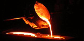
It is the most widely used metal casting manufacturing process accounting for a significant percentage of the total cast in weight. During the sand casting process, the material is heated to the correct temperature to melt and sometimes treated to modify the chemical composition to achieve the required material properties. Then the molten metal is poured into a mould with the desired shape cavity to cool down and solidify.
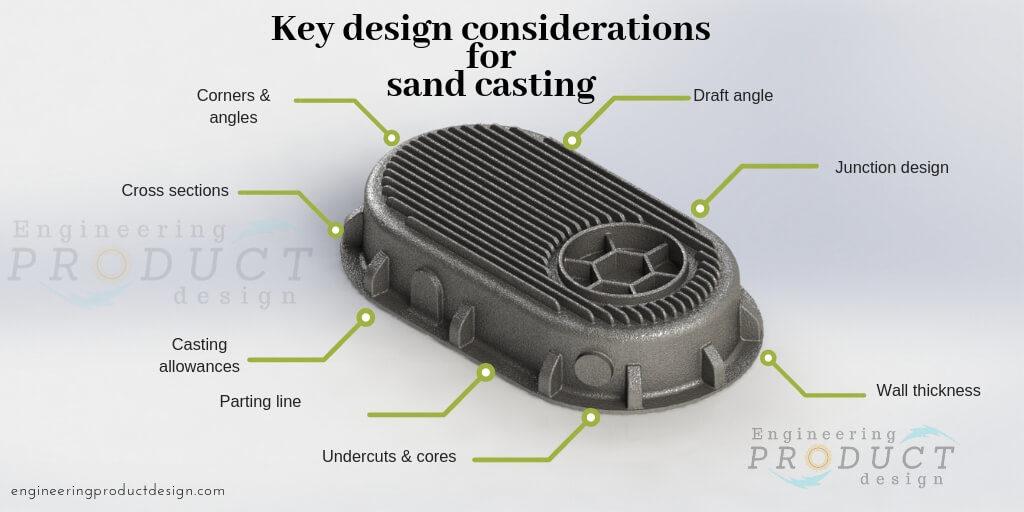
To produce the best quality sand castings at the lowest possible cost, the designers must carefully consider several process requirements and understand the limitation of sand casting. There are 8 key elements of sand casting, viz., draft angle, parting line, undercuts & cores, cross-sections, wall thickness, corners & angles, junction design, and casting allowance, that need to be taken into consideration to avoid the common pitfalls of mechanical engineers face during the sand casting process.
Defects or disadvantages will be an issue only if it affects the part’s functionality. So selecting a suitable manufacturing process is vital to satisfy the part functional requirement.
Characteristics of Sand casting
Sand casting is the most versatile among the manufacturing methods and gives engineers the freedom to design complex parts from an unlimited number of metals and alloys.
- Over 70% of all metal castings are produced via this process
- Sand casting can be produced in a wide range of sizes, from small statues to parts weighing over 100 tons
- Very complex parts can be produced easily and in one piece
- Low dimensional accuracy
- Poor surface finish
- Highly adaptable and could be used for handling mass production
How does the Sand casting process work?
Elements of the gating system
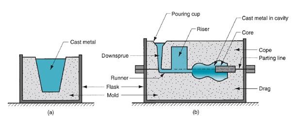
Sand casting is one of the most common metal casting processes, and its mould is made of two halves. Two halves are contained inside a flask box, the upper half is called the cope, and the bottom half is called the drag. The image below shows that the flask is divided into two halves. The line that separates the two halves is called the parting line.
Sand casting steps
The following are the seven main steps of the sand-casting cycle
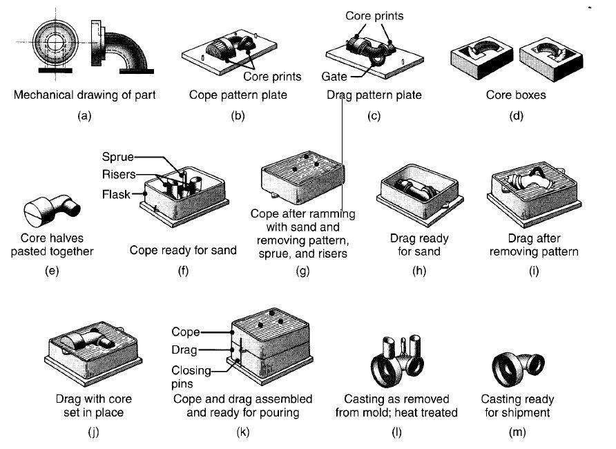
- Pattern-making step in which a replica of the object to be cast is made of suitable material. The pattern usually is oversized to allow for metal shrinkage during the cooling phase
- In the mould-making step, a sand mould is formed by packing sand into the mould around the pattern. The sand mould is divided into two halves, the top half is called the “Cope”, and the bottom is called the “Drag”. When the pattern is removed from the cavity, it forms remains for pouring the molten metal. Mould will have other features such as Sprue, runners, gate, pouring cup, riser etc., which will be discussed in detail later.
- The clamping step involves the two mould halves, Cope and Drag, securely clamped together, ready for pouring metal.
- Pouring molten metal is maintained at a set temperature. Molten metal is poured in quickly to avoid early solidification and
- Poured molten metal will begin to cool and solidify once inside the cavity. Most of the possible sand-casting defects are introduced at this solidification stage
- Once the cooling period elapses, the mould can be shaken out/broken off and casting
- Trimming involves cleaning and removing the section that is connected to the main part, such as the runner, Sprue etc
Advantages and disadvantages of sand casting
To understand any manufacturing process, first, careful consideration must be given not only to its advantages but, notably, to its potential limitations and process difficulties.
Advantages
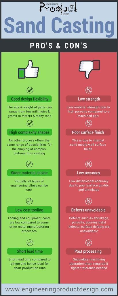
- Design flexibility – The size and weight of parts can range from a few millimetres & grams to meters & many tons. The size and weight of the cast are only limited by the restriction imposed by molten metal handling and supply. Hence large parts can be produced.
- High-complexity shapes – No other process offers the same possibilities for shaping complex features as casting that produces near-net-shape components.
- Wider material choice – Virtually all engineering alloys can be cast as long as it can be melted.
- Low-cost tooling – Tooling and equipment costs are low compared to other metal manufacturing processes. Hence making it one of the cheapest methods to achieve near-net-shape components
- Short lead time – Short lead time compared to others is ideal for short production runs.
- Less waste – Scrap metal can be recycled
Disadvantages
- Low material strength – Parts have Low material strength due to high porosity compared to a machined part.
- Low dimensional accuracy – Shrinking and the surface finish dimensional accuracy is very poor.
- Poor surface finishes – Due to internal sand mould wall surface texture.
- Defects unavoidable – Like any other metallurgical process, defects or quality variations such as shrinkage, porosity, pouring metal defects, surface defects are unavoidable. Porosity is higher on sand casts than in other casting processes, such as Die casting and investment casting.
- Post-processing – Secondary machining operation is often required if tighter tolerance is needed to interface with other mating parts. Processing cost is high compared to tooling and material cost
- Higher risk – Safety hazards to humans and environmental problems
- Production issues – Removal of the pattern of the thin and small parts is challenging
Sand casting design considerations
Sand casting is the most versatile among the manufacturing methods that enable to manufacture of very detailed and complex parts from an unlimited number of metals and their alloys.
A casting design would be useless unless the design can be made in the foundry, satisfying all the functional requirements within budget. The cost-effectiveness of the process depends highly on the design as this is reflected in the final cast. The decisions made during the design changes would make a big impact on the cost and some of the disadvantages of sand casting can be avoided by designing the part to suit casting. However, there are key sand casting design guidelines to be followed in order to keep costs down. Engineering product designers should understand the reasons as to why some of these techniques are used and consider those during the design stages of the cast.
Key design elements of sand casting
Contents covered in this article
Draft angle
Draft angle is the angle applied or allowed on all vertical faces of a pattern to aid easy removal from the sand mould without damaging its walls. The angle required depends on the moulding process, cast design and pattern depth inside the mould.
Design engineers often overlook this aspect of sand cast design even though it is critical for a successful cast. Allowing suitable draft angle and utilising the tapered surfaces in the design will increase castability and reduce tooling cost due to increased metal flow and ease of tooling.
If it does not critically affect the functionality of the design, a draft angle as per ISO standards will help produce cheaper and more consistent sand moulds. Generally, foundries as a rule of thumb use 1-1.5o of draft angle under normal conditions.
Parting line
A parting line in sand casting is the borderline in which draft angles change direction. Although the foundry will have the knowledge and experience of placing the parting line, engineering product designers should be aware of parting line placement as it dictates the quality and the cost of the cast. The parting line should be wide, short, horizontally flat and placed as low as possible. Change in parting line placement will affect core usage, gating placement, the weight of the cast and dimensional accuracy.
Undercuts & cores
Undercuts in sand casts are features that prevent and stop the pattern from being removed during the mould making stage. Usage of core sand loose pieces increases production time and cost. Parts should be designed in such a way that it reduces or eliminates core usage. Early parting line definition helps to understand the features to avoid undercuts.
Cross-sections
Uniform cross-sections, also referred to as uniform wall thickness is generally preferred but they are unfeasible in many engineering product designs. The principal requirement is not to leave thicker sections of the casting isolated when cooling. The thicker section takes longer to cool while all the metal around it had already solidified. As the thicker section continues to solidify it cannot “feed” from the sections around it leading to defects such as porosity or tearing. It is worth discussing with the foundry about the thickness limitation of your material before deciding.
Wall thickness
In sand casting, the volume to surface area ratio is critical in getting even solidification and avoiding the formation of cavities. Solidification is directly proportional to the square of volume/surface area ratio. Sections in the casting with low volume to surface area will solidify faster than sections with higher volume to the surface area.
It is good/ recommended practice to use ribs and gussets rather than increasing the overall thickness or adding thicker sections in load-bearing places. These not only add strength but also reduces localised thick walls and aid molten material flow. Isolated heavy sections can also induce stress concentrations and cause shrinkage and tears.
Corners & angles
Cooling characteristics of the cast and mould material have a major influence on the quality of sand castings. Sharp angles at intersections and corners produce local hot spots and provide sources of stress concentration. This causes the cast to distort, shrink and tear during and after the production process, hence should be eliminated by fillet radii.
Junction design
Since sand casting is a near-net shape manufacturing technique, the parts can often be very complex in shape and contain lots of junctions. These junctions are generally grouped under five types viz., L, X, V, Y and X-T junctions.
They create localised mass concentrations, and these can create defects such as shrinkage, tears and cracks. Ideally, these junctions should be designed in a way to reduce or eliminate localised mass concentrations.
Casting allowances
Most metals such as steel, aluminium, magnesium, zinc and copper shrink when they solidify and need to be considered and managed carefully. The amount of shrinkage depends on the freezing point of the material and the volume to surface area ratio of the product.
Machining allowance should be added for mating interfaces of two sand cast parts and curved edges should be avoided at the interface. Recommendations for the machining allowances are included in the published standard ISO 8062.
Recommended reading
- Kalpakjian, S., & Schmid, S. R. (2009). Manufacturing Engineering & Technology (Sixth edition ed.). London: Pearson.