Binder Jetting (BJ) is an advanced Additive Manufacturing (AM) technique where a liquid binder selectively joins powder particles to form a 3D object. Unlike other AM methods, BJ does not require heat for fusing materials, setting it apart by combining binder and powder to create intricate and diverse structures.
Contents covered in this article
What is Binder Jetting?
Binder Jetting (BJ) is one of seven Additive Manufacturing techniques in which a binding liquid is selectively deposited by the printer head to join powder material to form a 3D part. Among the additive manufacturing technologies today, binder jetting is unique because it does not employ heat during the process like others to fuse the material.
Historical Background
Binder Jetting was first developed at MIT in the 1990s as part of a research project on additive manufacturing. Over the years, it has evolved significantly, with various companies improving the technology and expanding its applications. Early developments focused on using the process for rapid prototyping, but it has since grown to be used in full-scale production in industries like aerospace, automotive, and medical devices.
Technical Specifications
- Layer Thickness: Typically ranges from 50 to 200 microns.
- Print Speed: This can be up to 10 layers per minute, depending on the machine and part complexity.
- Resolution: XY resolution is often around 80-100 microns.
- Build Volume: Varies by machine, with industrial models capable of printing parts several meters in size.
Types of Binder Jetting
The binding agent helps combine the material to form the object, which can be classified into four types. Binders are critical to a successful BJ process. The type of binder used depends on the type of powder or system being used or customer application requirements.
One of the pioneers of this binder technology, ExOne, uses the following binders.
- Furan Binder – These are often used for sand casting moulds and cores.
- Silicate Binder: This type of binder is suitable for high-temperature applications.
- Phenolic Binder: Phenolic binder provides strength and chemical resistance.
- Aqueous-Based Binder: This eco-friendly option is often used with ceramic and metal powders.
How does Binder jetting work?
Step 1 – Transfer of CAD Data
Conversion to STL File: The first step in the Binder Jetting process is converting the 3D model designed in Computer-Aided Design (CAD) software into a standard tessellation language (STL) file. This file format approximates the shape of the object using triangular facets.
Slicing: The STL file is imported into slicing software, which slices the model into thin horizontal layers based on the chosen layer thickness. This creates a series of 2D cross-sectional data that the printer will follow layer by layer.
Toolpath Generation: The slicing software generates tool paths for the print head to follow for each layer, specifying where the binder will be deposited on the powder bed.
Printer Configuration: Configure printer settings, including layer thickness, binder flow rate, print speed, and curing parameters based on the material and desired part characteristics.
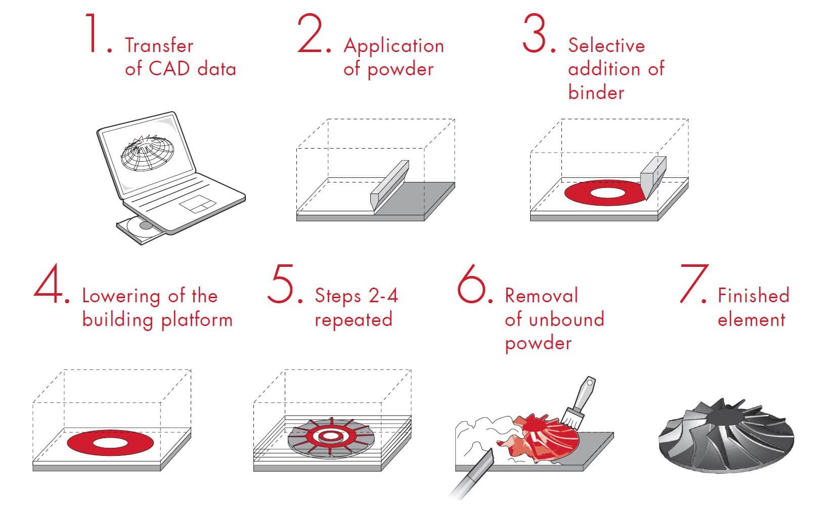
Step 2 – Application of Powder
Powder Delivery: The printer’s powder supply system dispenses a controlled amount of powder onto the build platform. Depending on the application, the material can be metals, ceramics, polymers, or sand.
Spreading: A recoater or roller spreads the powder evenly across the build platform to form a uniform layer. The slicing data define the thickness of this layer and typically ranges from 50 to 200 microns.
Compaction: In some systems, the powder layer may be compacted slightly to ensure uniform density and minimise layer roughness.
Step 3 – Selective Addition of Binder
Print Head Movement: The print head, equipped with nozzles, moves over the powder bed according to the toolpaths generated from the slicing software. It selectively deposits binder droplets onto specific areas, adhering to the digital model’s cross-sectional design for that layer.
Binder Deposition: The binder acts as an adhesive, binding the powder particles together where it is applied. The droplet size, deposition rate, and binder properties (e.g., viscosity & drying time) are controlled to achieve the desired part resolution and mechanical properties.
Layer Patterning: The deposition pattern can include fine details and complex geometries, with the binder only applied where solid material is needed.
Step 4 – Lowering of the Building Platform
Layer Advancement: After the binder bounds each layer of powder, the build platform lowers by the thickness of one layer (typically 50-200 microns).
Repositioning: The recoater or roller returns to its starting position, ready to apply the next layer of powder. This step is synchronised with the binder deposition to maintain accuracy and ensure the stability of the growing part.
Step 5 – Repetition of Steps 2-4
Layer-by-Layer Construction: Steps 2 (Application of Powder), 3 (Selective Addition of Binder), and 4 (Lowering of the Building Platform) are repeated for each layer of the build until the entire object is formed. This repetitive process builds the part from the bottom up, layer by layer.
Continuous Monitoring: The process is monitored for consistency in powder application, binder deposition, and platform movement. Adjustments are made as needed to ensure part quality.
Interlayer Bonding: The binder in successive layers also interacts with the previously deposited layers, contributing to the part’s overall strength and integrity.
Step 6 – Removal of Unbound Powder
Depowdering: Once the printing process is complete, the build platform is raised to expose the finished part, which is still surrounded by unbound powder.
Powder Extraction: The unbound powder is carefully removed using brushes, air blowers, or vacuum systems. The powder can often be collected and recycled for future prints.
Fine Cleaning: For complex parts, additional cleaning methods may be used to remove residual powder from intricate details and internal cavities, ensuring that all unbound material is cleared away without damaging the part.
Step 7 – Finished Element
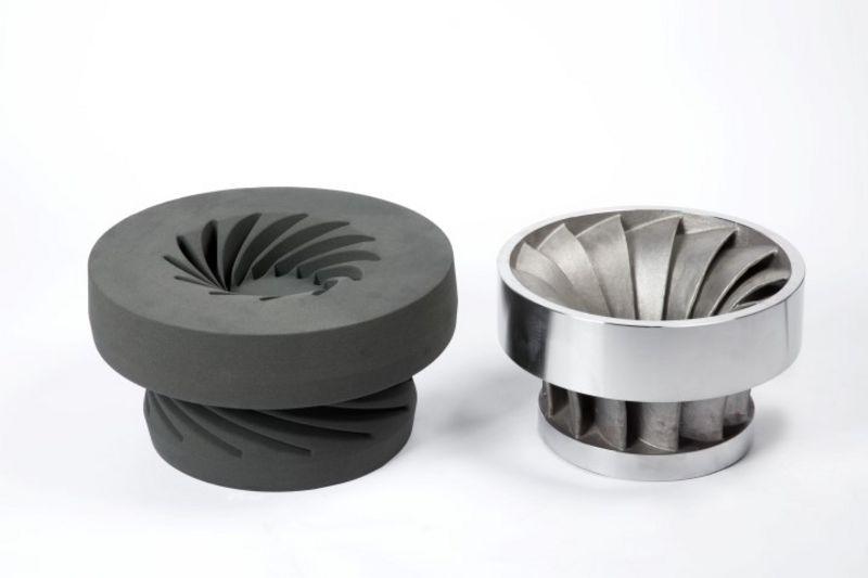
Green Part Handling: The part, now a green body, has been freed from unbound powder but still contains the binder, giving it a fragile and “green” status. It has sufficient integrity to be handled but lacks full mechanical strength.
Post-Processing: The green part undergoes various post-processing steps, such as sintering, infiltration, and surface finishing, to achieve the final desired properties.
Sintering: Heat the green part in a furnace to bond powder particles together. For metal parts, sintering temperatures are usually between 1100°C and 1600°C. This step enhances mechanical properties and reduces porosity.
- Controlled Atmosphere: Sintering often requires a controlled atmosphere, such as vacuum or inert gas, to prevent oxidation and achieve optimal material properties.
Infiltration: Introduce a secondary material (e.g., bronze) into the part’s pores to enhance strength and density. This is done by heating the green part in a furnace with the infiltrant, allowing the material to flow into the voids.
- Infiltration Techniques: Methods can include capillary action, gravity, or pressure-assisted infiltration, depending on the material and desired final properties.
Surface Finishing: Apply finishing techniques to achieve the desired surface quality and dimensions.
- Sanding: Smoothens the surface by removing minor imperfections and roughness.
- Machining: Further refine dimensions and surface finish using tools like lathes or milling machines.
- Coating: This process adds protective layers or aesthetic finishes, such as painting or plating, to enhance appearance or functionality.
Final Inspection: The finished element is inspected for dimensional accuracy, surface quality, and structural integrity. Quality checks ensure that the part meets all specifications and standards before it is ready for use.
Descriptive video of a Binding Jetting process by Voxeljet
Materials and Properties
Materials Used in Binder Jetting
Binder Jetting supports a wide range of materials:
- Metals: Stainless steel, Inconel, copper, titanium.
- Polymers: Nylon, PMMA (polymethyl methacrylate).
- Ceramics: Silica, alumina, zirconia.
- Sand: Used for making moulds in casting.
Each material has specific properties that influence the choice of binder and post-processing techniques. For example, metal parts often require sintering or infiltration to achieve desired mechanical properties, while sand moulds are typically used as-is for casting.
Properties of Binder Jetting Parts
- Strength: Depends on the binder and material; metal parts are comparable to cast or wrought components after post-processing.
- Density: This can be controlled through the amount of binder and compaction during post-processing.
- Surface Finish: It typically ranges in roughness from 5 to 25 microns and can be improved through polishing or coating.
Comparison with other AM technologies
Binder Jetting vs. Selective Laser Sintering (SLS)
Binder Jetting (BJ) uses a liquid binder to join powder materials layer-by-layer without heat, enabling a broader material range (metals, polymers, ceramics) and faster print speeds. Selective Laser Sintering (SLS) employs a laser to sinter powdered material, achieving high-strength, heat-resistant parts primarily in polymers and metals. BJ excels in cost-effectiveness for complex, colour, or sand parts, while SLS provides superior mechanical properties for functional prototypes and production parts. Table 1 shows key differences:
| Feature | Binder Jetting (BJ) | Selective Laser Sintering (SLS) |
| Materials | Metals, Ceramics, Sand | Polymers, Metals |
| Post-Processing | Sintering, Infiltration | Minimal |
| Applications | Prototypes, Sand Moulds | Functional Prototypes |
| Build Speed | Faster | Moderate |
Binder Jetting vs. Fused Deposition Modelling (FDM)
Binder Jetting (BJ) uses a liquid binder and powders, enabling intricate geometries and full-colour parts suitable for metals, ceramics, and sand. Fused Deposition Modeling (FDM) melts and extrudes thermoplastic filaments, offering low-cost, user-friendly desktop printing ideal for plastic prototyping. BJ is advantageous for complex, larger-scale applications requiring multiple materials, whereas FDM is preferred for straightforward, low-cost prototypes and parts with moderate detail. Table 2 highlights distinctions:
| Feature | Binder Jetting (BJ) | Fused Deposition Modeling (FDM) |
| Materials | Metals, Ceramics, Sand | Thermoplastics |
| Detail Resolution | High | Moderate |
| Applications | Industrial Parts, Moulds | Rapid Prototypes, Hobbyist Models |
| Build Speed | Faster | Slower |
Binder Jetting vs. Stereolithography (SLA)
Binder Jetting (BJ), with its binder and powder process, supports a variety of materials and large build volumes at lower costs. Stereolithography (SLA) uses a UV laser to cure photopolymer resins, delivering high-resolution parts with smooth surfaces suitable for detailed prototypes and moulds in polymers. BJ excels in producing large, complex, multi-material parts, while SLA is superior for fine-detail models and functional prototypes with excellent surface finish. Table 3 compares these techniques:
| Feature | Binder Jetting (BJ) | Stereolithography (SLA) |
|---|---|---|
| Materials | Metals, Ceramics, Sand | Photopolymer Resins |
| Resolution | Moderate | High |
| Applications | Industrial Moulds, Prototypes | Dental, Jewelry, Prototypes |
| Surface Finish | Rough | Smooth |
Binder Jetting vs. Direct Metal Laser Sintering (DMLS)
Binder Jetting (BJ) builds parts by depositing a binder onto the powder, suitable for various materials, including metals, ceramics, and sand. Direct Metal Laser Sintering (DMLS) uses a laser to sinter metal powder layer by layer, producing fully dense, functional metal parts. BJ allows faster builds and larger volumes with lower material costs, ideal for prototypes and non-load-bearing parts. In contrast, DMLS achieves superior strength and precision, fitting high-performance aerospace and medical applications. Table 4 outlines key contrasts:
| Feature | Binder Jetting (BJ) | Direct Metal Laser Sintering (DMLS) |
| Materials | Metals, Ceramics, Sand | Metals |
| Part Density | Moderate | High |
| Applications | Prototypes, Large Parts | Functional Metal Parts |
| Cost | Lower | Higher |
Binder Jetting vs. Material Jetting
Binder Jetting (BJ) and Material Jetting (MJ) are both additive manufacturing technologies that use droplets to build parts layer-by-layer, but they differ significantly in their processes and applications. Binder Jetting deposits a liquid binder onto a powder bed, bonding powder particles to form each layer. It supports various materials, including metals, ceramics, and sand, and is ideal for complex shapes, large-scale parts, and sand-casting moulds. Material Jetting involves depositing droplets of build material directly from print heads, curing them with light or heat to create highly detailed parts in photopolymers or waxes, making it suitable for fine-detail prototypes, multi-material parts, and medical models. Table 1 provides a comparison:
| Feature | Binder Jetting (BJ) | Material Jetting (MJ) |
| Process | Deposits binder onto a powder bed | Deposits build material directly |
| Materials | Metals, Ceramics, Sand | Photopolymers, Waxes |
| Part Detail | Moderate | High |
| Applications | Sand Casting Moulds, Large Parts | Prototypes, Multi-Material Parts |
| Cost | Lower | Higher |
- Layer Thickness: BJ (50-200 microns) vs. MJ (16-32 microns)
- Material Utilization: BJ (recyclable powder) vs. MJ (efficient use of photopolymers)
- Part Accuracy: BJ (±0.2 mm) vs. MJ (±0.1 mm)
- Surface Roughness: BJ (10-25 µm Ra) vs. MJ (1-5 µm Ra)