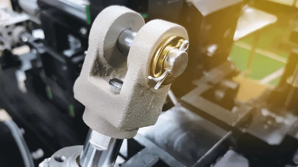
Clevis pin joints are vital in mechanical systems. This guide explores how to optimise their design for strength, durability, and long-term reliability.
Contents covered in this article
You’ll often need simple, strong, and reliable connections when designing mechanical systems. Enter the clevis pin joint—a versatile and staple engineering solution for decades. Whether you’re working on heavy machinery, aerospace structures, or automotive systems, understanding how to optimise these industrial fasteners is crucial for ensuring your designs stand up to the rigours of real-world use.
This comprehensive guide will provide insights on how to make that happen. We’ll discuss the essentials of clevis pin joints, explore their various types, explain the complex stresses they endure, and suggest preventing common failure modes. Let’s start.
Types of Clevis Pin joints
Before optimising, you must familiarise yourself with the different types of clevis pins. Each type has its own strengths and ideal applications. Clevis pin sizes vary widely depending on the specific requirements of your project, so understanding these different types will help you make informed decisions about which size and style to use:
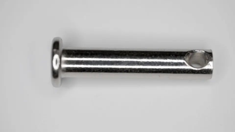
- Straight clevis pins: These are your standard cylindrical pins. They’re versatile and suitable for many applications where the load is primarily shear.
- Shoulder clevis pins: Featuring a larger diameter section, shoulder clevis pins provide additional bearing surface and help distribute loads more evenly.
- Headed clevis pins: With a head on one end, these pins are easier to install and remove, making them ideal for applications requiring frequent maintenance.
- Threaded clevis pins: These work like machine screws and allow for secure fastening using a nut, providing excellent retention in high-vibration environments.
- Quick-release pins: These attachments typically feature a ball-detent mechanism for easy insertion and removal. These pins work great when rapid assembly and disassembly are crucial.
Choosing the correct type of clevis pin for your application is the first step in optimising your joint design. When selecting, consider factors like load type, assembly requirements, and maintenance needs.
| Pin Type | Pros | Cons |
|---|---|---|
| Straight Clevis Pins | – Simple design – Easy to install – Cost-effective | – Can slide out if not secured – Limited load-bearing capacity |
| Shoulder Clevis Pins | – Precise positioning with shoulder – Prevents lateral movement – Better load distribution | – More complex design – Typically more expensive than straight pins |
| Headed Clevis Pins | – Offers a positive stop at one end – Prevents over-insertion – Can withstand higher loads | – Requires more space for installation due to the head – Slightly more expensive than straight pins |
| Threaded Clevis Pins | – Secure fit with nuts – Adjustable length with threading – Prevents unintentional release | – More time-consuming to install and remove – Higher cost due to complexity |
| Quick Release Pins | – Fast and easy installation/removal – Ideal for frequent assembly/disassembly – No additional hardware required | – Lower shear strength than other types – More expensive due to specialised design |
Types of Stresses in a Clevis Pin Joint
Understanding the stresses a clevis pin experiences is crucial for effective design. Let’s break down the four primary types of stress you’ll need to account for:
Shear Stress
Shear stress is often the most significant stress in a clevis pin joint. It occurs perpendicular to the pin’s axis and tries to cut the pin in half. When calculating shear stress, you must consider the applied load, the pin’s cross-sectional area, and any stress concentration factors.
Your ability to accurately calculate and account for shear stress will determine the joint’s strength and reliability. Generally, a double shear configuration, where the pin passes through three plates, is preferable to single shear, as it distributes the load more evenly.
Since a clevis pin is often loaded in shear, it is essential to calculate the shear stress acting on the cross-sectional area of the pin.
\[\tau = \frac{F}{A}\]
where:
- τ= shear stress
- F = applied force
- A = cross-sectional area of the pin
Bending Stress
While often overlooked, bending stress can be significant, especially in single-shear configurations or when there’s a gap between the clevis plates. Bending causes the pin to flex, creating tensile stress on one side and compressive stress on the other. To minimise bending stress:
- Reduce any gaps between mating parts
- Increase the pin diameter, but be mindful of the trade-off with increased hole size
- Consider using a shoulder pin to provide additional support
Neglecting bending considerations can lead to premature failures and underperforming joints. As you refine your approach to bending stress, you’ll find that small design tweaks can yield significant improvements in joint performance.
Depending on the application, clevis pins can also experience bending loads. Bending stress is calculated using:
\[σ_b = \frac{M}{Z}\]where:
- σ_b = bending stress
- M = bending moment
- Z = section modulus of the pin’s cross-section
Bearing Stress
Bearing stress occurs when the pin contacts the clevis and the joined component. It’s a compressive stress that can lead to deformation or wear over time. To manage bearing stress:
- Ensure adequate contact area between the pin and the holes.
- Consider the material properties of both the pin and the mating components.
- Use hardened pins or bushings in high-load applications.
Bearing-related issues can significantly impact your joint’s longevity and performance. As you work on your designs, consider how surface finish, lubrication, and potential misalignment can help minimise bearing stress over time.
Bearing stress occurs when the pin bears against the clevis’ inner walls due to an applied load. It is important to ensure that localised crushing does not occur.
\[σ_b = \frac{F}{A_b}\]where:
- σ_b = bearing stress
- F = force applied by the pin on the clevis
- A_b = projected contact area between the pin and clevis
Tensile Stress
While less common, tensile stress can occur in specific clevis pin configurations, mainly when using threaded pins. It’s crucial to account for this stress when using them, as it can lead to pin elongation or failure if not adequately managed.
In some cases, clevis pins may be subjected to tensile loads. The tensile stress is calculated as:
\[σ_t = \frac{F}{A}\]where:
- σt\sigma_tσt = tensile stress
- F = applied tensile force
- A = cross-sectional area
Train yourself to consider all potential stress states, even those that might seem secondary at first glance. This comprehensive approach will serve you well, especially when encountering unique or challenging joint configurations. After all, engineering isn’t just about addressing the obvious. It also anticipates and mitigates all potential modes of failure.
Failure Modes
Understanding potential failure modes is key to preventing them. Here are the primary ways a clevis pin joint might fail:
Shear Failure
Shear failure occurs when the applied load exceeds the pin’s shear strength. It results in a clean break across the pin’s cross-section. To prevent this, properly size your pin based on shear stress calculations and use materials with adequate shear strength. You could also implement double-shear configurations for better load distribution, as mentioned.
Bending Failure
Excessive bending can cause the pin to yield or fracture. Signs of impending bending failure include permanent deformation of the pin. Mitigate this risk by minimising gaps in the joint and using tougher pin materials. Additionally, opting for larger diameter pins could also work.
Feel free to explore innovative solutions. Some of the most effective designs come from thinking outside the traditional engineering box.
Bearing Fatigue Failure
Over time, cyclic loading can cause the pin holes to elongate or the pin surface to wear. This type of failure can surprise you as it develops gradually. Combat bearing fatigue by:
- Ensuring proper lubrication
- Using materials with good wear resistance
- Designing for lower bearing stresses
- Implementing regular inspection and maintenance schedules
Tackling this type of failure requires a long-term perspective on your designs. While in the design phase, strive for initial strength and long-term reliability. Doing so lets you create solutions that meet immediate performance needs and stand the test of time.
Design Considerations
Now that you understand the stresses and failure modes, let’s examine key design considerations that will help you create optimal clevis pin joints.
Material Selection
Choosing the right material is crucial for joint performance. Consider these factors:
- Strength requirements, including yield strength, ultimate strength, and fatigue strength
- Environmental conditions (e.g., corrosion resistance, temperature extremes)
- Weight constraints
- Cost and availability
Popular materials include alloy steels (e.g., AISI 4340), a vast range of stainless steel (e.g., 17-4 PH), and titanium alloys for aerospace applications. Each has its pros and cons, so weigh your options carefully.
Here’s a table of some popular materials used in clevis pin design, along with their key properties:
| Material | Tensile Strength (MPa) | Shear Strength (MPa) | Yield Strength (MPa) | Yield Strength (MPa) | Yield Strength (MPa) | Common Uses |
|---|---|---|---|---|---|---|
| Mild Steel (AISI 1018) | 440 | 260 | 370 | 120 | Low | General-purpose mechanical parts, pins |
| Stainless Steel (AISI 304) | 515 | 300 | 205 | 160 | High | Corrosion-resistant components, marine and food industry |
| Alloy Steel (AISI 4140) | 655 | 500 | 415 | 197 | Moderate | High-strength mechanical parts, automotive and industrial applications |
| Aluminium Alloy (6061-T6) | 310 | 200 | 275 | 95 | Moderate to High | Lightweight components, aerospace, and structural applications |
| Brass (C36000) | 380 | 210 | 110 | 90 | Moderate | Electrical components, low-load pins and fasteners |
| Titanium Alloy (Grade 5) | 900 | 550 | 830 | 350 | Excellent | High-strength, lightweight applications, aerospace |
| Phosphor Bronze | 600 | 350 | 275 | 100 | High | Corrosion-resistant applications, marine, electrical pins |
Key
- Tensile Strength: The maximum stress the material can withstand before breaking.
- Shear Strength is the material’s ability to resist shearing forces, which is critical for clevis pin applications.
- Yield Strength: The stress at which the material begins to deform permanently.
- Hardness: Indicates the material’s resistance to surface wear or deformation.
- Corrosion Resistance: This is important for pins exposed to harsh environments like marine or chemical exposure.
Pin Geometry
Every dimension and feature of your pin can impact the joint’s performance. Key considerations include:
- Diameter: Larger diameters increase strength but require larger holes, which can weaken the clevis.
- Length: Ensure the pin is long enough to engage with all components fully but not so long as to introduce unnecessary weight.
- Shoulder design (if applicable): Properly sized shoulders can significantly reduce bending stresses.
- End features: Consider how the pin will be retained (e.g., cotter pins, circlips, threaded ends).
The interplay between pin diameter, length, and end features creates a complex design space ripe for optimisation. Experiment with different combinations while keeping your specific application requirements in mind.
| Pin Diameter (mm) | Pin Length (mm) | Shear Strength (N) | Bearing Area (mm²) | Recommended Load (N) |
| 5 | 20 – 50 | 9,000 | 196 | 4,500 |
| 6 | 20 – 60 | 13,500 | 282 | 6,750 |
| 8 | 30 – 80 | 24,000 | 503 | 12,000 |
| 10 | 40 – 100 | 37,500 | 785 | 18,750 |
| 12 | 50 – 120 | 54,000 | 1130 | 27,000 |
| 16 | 60 – 150 | 96,000 | 2010 | 48,000 |
| 20 | 80 – 200 | 150,000 | 3140 | 75,000 |
| Pin Diameter (inches) | Pin Length (inches) | Shear Strength (lbf) | Bearing Area (in²) | Recommended Load (lbf) |
| 3/16 | 3/4 – 2 | 1,200 | 0.037 | 600 |
| 1/4 | 3/4 – 2 1/2 | 2,100 | 0.049 | 1,050 |
| 5/16 | 1 – 3 | 3,200 | 0.077 | 1,600 |
| 3/8 | 1 1/4 – 4 | 4,700 | 0.110 | 2,350 |
| 1/2 | 1 1/2 – 5 | 8,500 | 0.196 | 4,250 |
| 5/8 | 2 – 6 | 13,500 | 0.307 | 6,750 |
Key
- Pin Diameter: Select based on load requirements and space constraints.
- Pin Length: This depends on the thickness of the fastened parts and additional clearances.
- Shear Strength: Calculate based on material properties, typically mild steel or alloy.
- Bearing Area: Consider how the load distributes over the surface where the pin bears against other components.
- Recommended Load: This value helps engineers choose a pin size based on the expected load to ensure a safety factor is applied.
Safety Factor
While using a very high safety factor might be tempting, it can lead to overdesigned, heavy, and costly joints. Keep these questions in mind to strike a great balance between safety and function:
- How critical is the application?
- Are your load predictions highly accurate?
- Are the material properties variable?
- Is there a potential for misuse or abuse?
An overly conservative approach can lead to bulky, expensive designs, while cutting it too close may risk failure. For guidance, typical safety factors range from 1.5 to 3, but it’s best to consult relevant industry standards and regulations.
Load Distribution
Optimising load distribution can significantly improve joint performance. Here are some strategies you could apply in your design:
- Using double shear configurations where possible
- Ensuring tight tolerances to minimise gaps
- Considering bushing inserts to distribute bearing loads
- Designing surrounding structures to provide uniform loading
By managing load distribution properly, you can create industrial fasteners that are stronger, more durable, and less prone to fatigue failures.
Carefully considering each aspect of your design helps you create exceptional joints. The insights above can help you create products that exceed performance expectations in various manufacturing processes and industrial applications.
Conclusion
Designing optimal clevis pin joints is a multifaceted challenge that requires a deep understanding of mechanics, materials, and practical design considerations. As you apply these principles in your work, you’ll find that well-designed clevis pin joints can very well be the unsung heroes of your mechanical systems—simple yet robust and reliable.
At the same time, it’s important to note that the best designs often come through iteration. So, always create a prototype, test, and refine your designs. These steps will help you gain valuable insights as you develop your current and future projects.