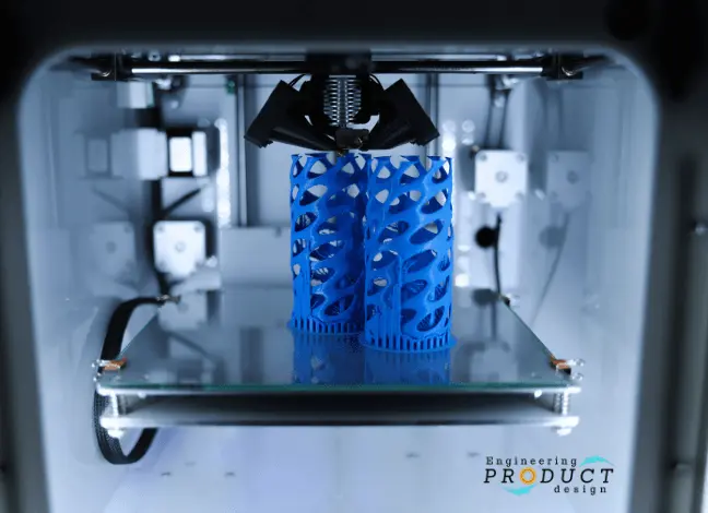
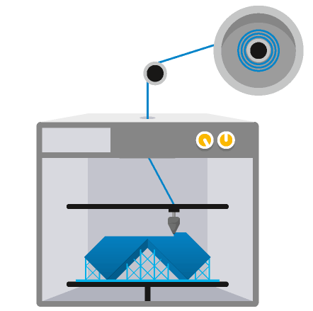
In material extrusion, plastic filament is fed through a heated extruding nozzle and deposited onto the building platform layer by layer.
Contents covered in this article
What is Material extrusion?
Material extrusion is an additive manufacturing technique using continuous thermoplastic or composite material filament to construct 3D parts. The plastic filament is fed through an extruding nozzle, which heats the material to a molten state and then deposits it layer by layer onto the building platform to create a 3D part.
Material extrusion is now the most popular additive manufacturing process in terms of availability for general consumer demand and quality under the Fused Deposition Modeling (FDM) type of printer.
As per ISO/ASTM 52900:2021, it is one of the 7 Additive manufacturing processes.
How does Material Extrusion work?
Material extrusion printers typically have a build platform and a printing nozzle head gantry in a three-axis system. The schematic image shows that the printing head gantry moves in X & Y while the build platform moves in the Z-axis. Variants of this printer configuration include Cartesian, CoreXY, delta, SCARA, belt, H-bot, and polar.
Part Preparation – The 3D model is converted into layer-based information – Read our “How AM works?” article to understand how the model is converted by slicing software.
Machine set up – The printer is loaded with thermoplastic filament in spools or pellets. This will depend on the printer manufacturer and material extrusion types.
Printing – The extrusion nozzle head move along the X-Y plane which allows the nozzle tip to move and will start depositing the material layer by layer in predefined areas to cool and solidify.
The following video by Solid Concepts explicitly outlines the Material extrusion process.
FDM technology (Source:Solid concepts)
Material extrusion types
Material extrusion technology was first developed in the 1980s by S. Scott Crump under the registered name of Fused Deposition Modelling (FDM). The term fused deposition modelling (FDM) and its abbreviation FDM are trademarked by Stratasys Inc., a company co-founded by Scott Crump.
Since FDM’s inception, new material extrusion technologies have emerged with slight variations.
Advantages and Disadvantages of Material Extrusion
Advantages of Material Extrusion
- Wide selection of print material
- Easily understandable printing technique
- Easy and user-friendly method of material change
- Low initial and running costs compared to other AM techniques
- Comparably faster print time for small and thin parts
- Printing tolerance of +/- 0.1 mm (+/- 0.005″)
- No supervision required
- Small equipment size compared to other AM
- Comparably low-temperature process
Disadvantages of Material Extrusion
- Visible layer lines
- The extrusion head must continue moving, or else the material bumps up
- Supports may be required
- Poor part strength along the Z-axis (perpendicular to the build platform)
- Finer resolution and wider area increase print time.
- Susceptible to warping and other temperature fluctuation issues such as delamination
- Toxic print materials
Material extrusion materials
Although a variety of materials can be used in material extrusion, thermoplastics like acrylonitrile butadiene styrene (ABS), aliphatic polyamides (PA, also known as Nylon), high-impact polystyrene (HIPS), polylactic acid (PLA), and thermoplastic polyurethane are the most popular.
Lately, material extrusion 3D printing has successfully extruded paste-like materials like ceramics, concrete, and chocolate, as well as plastic materials like polyether ether ketone (PEEK) and polyetherimide (PEI).
As long as the base thermoplastic material is present sufficiently to ensure fusion between the layers, material extrusion can also be used with composite materials. This implies that components made of printed materials can contain components made of wood, metal, or even carbon fibre.
| Material | Key properties |
|---|---|
| ABS (Acrylonitrile Butadiene Styrene) | Strength, Impact Resistance, Durability |
| PLA (Polylactic Acid) | Biodegradability, Ease of Printing, Low Warping |
| Nylon (Aliphatic Polyamides) | Toughness, Flexibility, Chemical Resistance |
| HIPS (High-Impact Polystyrene) | Rigidity, Impact Resistance, Smooth Finish |
| TPU (Thermoplastic Polyurethane) | Elasticity, Abrasion Resistance, Flexibility |
| PEEK (Polyether Ether Ketone) | High-Temperature Resistance, Chemical Resistance |
| PEI (Polyetherimide) | High Strength, Flame Resistance, Dimensional Stability |
| Fiber Reinforced Filaments | Enhanced Strength, Stiffness, Lightweight |
| Metal-Infused Filaments | Metallic Finish, Conductivity, Mechanical Strength |
| Wood-Infused Filaments | Natural Appearance, Texture, Wood-like Characteristics |
| Ceramic Filaments | Heat Resistance, Smooth Surface Finish, Non-conductive |
Material extrusion applications
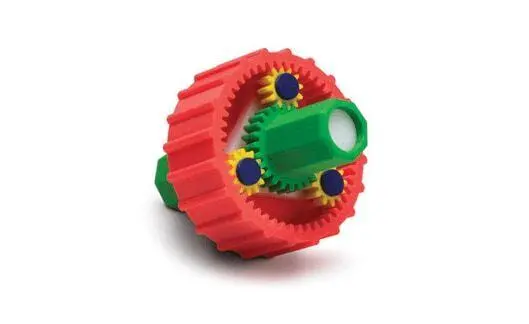
Material extrusion can produce non-functional prototypes, production jigs, and small pre-production batches for testing and concept models.
During the embodiment design stages of product design, it can make rapid prototyping for multiple iterations cost-effective.
| Material | Applications |
|---|---|
| ABS (Acrylonitrile Butadiene Styrene) | Prototyping, Automotive Parts, Electronics Casings |
| PLA (Polylactic Acid) | Prototyping, Medical Devices, Food Packaging |
| Nylon (Aliphatic Polyamides) | Gears, Bearings, Functional Prototypes |
| HIPS (High-Impact Polystyrene) | Prototyping, Models, Display Items |
| TPU (Thermoplastic Polyurethane) | Flexible Components, Phone Cases, Footwear |
| PEEK (Polyether Ether Ketone) | Aerospace Components, Medical Implants, Automotive |
| PEI (Polyetherimide) | Electrical Components, Aerospace Parts, Automotive |
| Carbon Fiber Reinforced Filaments | Automotive Parts, Aerospace Components, Prosthetics |
| Metal-Infused Filaments | Jewellery, Prototyping for Metal Parts, Decorative Items |
| Wood-Infused Filaments | Furniture Prototyping, Decorative Objects, Artifacts |
| Ceramic Filaments | Prototyping for Ceramics, Artwork, Custom Pottery |
Fused Deposition Modeling is a 3D printing technology that creates parts from the plastic filament by melting and then depositing them in layers.
Fused Deposition Modeling (FDM)
Developed by Stratasys, FDM is one of the earliest and most well-known forms of material extrusion. It involves melting thermoplastic filaments and depositing them layer by layer to create a 3D object.
What is Fused Deposition Modeling (FDM)?
Fused deposition modeling is an additive manufacturing technology that creates 3D components using a continuous thermoplastic or composite material thread in filament form. An extruder feeds the plastic filament through an extruding nozzle, which is melted and then selectively deposited layer by layer onto the build platform in a predetermined automated path.
FDM, also known as Fused Filament Fabrication (FFF), is a Material extrusion technology, one of the seven main types of additive manufacturing technologies. FDM is the most widely used 3D printing technique, with the most 3D printer users globally, and is typically the first 3D printing technology to which people are exposed.
Scott Crump pioneered the process in the 1980s under the registered term fused deposition modelling (FDM). Stratasys Inc, a business co-founded by Scott Crump, owns the trademark fused deposition modelling (FDM) and its abbreviation FDM.
How does Fused deposition modeling work?
FDM printer overview
The schematic below shows a basic overview of an FDM printer. It consists of two extruding nozzles on linear slides, a build platform on another linear slide and supports for plastic filament spools.
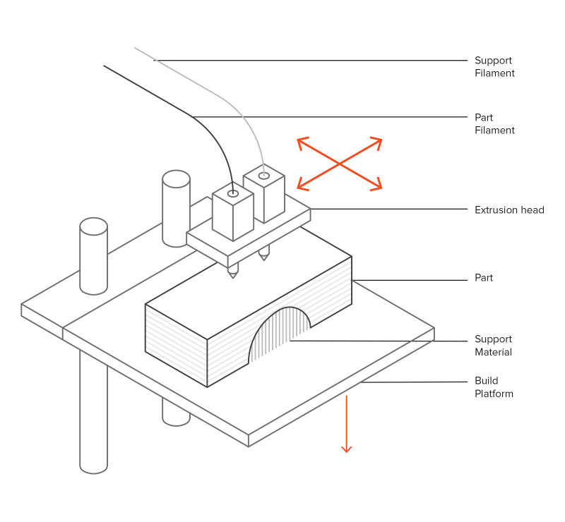
The extruders are called Model and Support extruders. As the name implies, the model extruder prints the material for the 3D shape, while the support extruder prints the supports. They can either have the same material or different materials. Hobbyist printers have a single extruder and use the same material for both model and support.
Depending on the type and brand of FDM printer, the XYZ movement could come from the extruders and the build platform. As the schematic shows, in this version, the extruder head gantry moves in X & Y while the build platform moves in Z-axis. In some versions, the print head moves in X and Z while the build platform moves in Y.
Fused Deposition Modeling process steps
Part preparation step

The first few steps are similar to any other additive manufacturing technology, starting with build preparation software. The initial stage is to import the design file and choose options for the build, such as layer height, orientation and infill percentage. The software then computes sections and slices the part into several layers. The program then creates extruder paths and building instructions based on the sectioning data to drive the extrusion heads.
Depending on the printer and the manufacturer, the above process will be different, but the core step of 3D file conversion into layer-based information is the same.
FDM machine set-up step
The printer is loaded with a thermoplastic filament spool for both model and support extruders. Generally, the build platform is heated and maintained at a higher temperature to control the cooling of the extruded material. Extruders are heated, and when the nozzle reaches the required temperature, the head will start pushing and melting the filament into a small ribbon roughly the size of a human hair.
FDM printing step
The extrusion head gantry and the build platform are on a three-axis system, which allows the nozzle tip to move in three directions in space. The extruder will start depositing the material layer by layer in predefined areas to cool and solidify. Sometimes the material cooling is assisted using cooling fans mounted to the extrusion head.
Multiple passes are necessary to fill a region within a layer. When the gantry completes a layer, the build platform or the heads will move the Z-axis by the layer height. Then the above process starts again to deposit a new later. This procedure continues until all the layers are built.
FDM part removal
Like any other 3D printing process, the next stage involves removing parts from the build platform and cleaning them by removing all supports.
Post-processing
Part can then be further processed, remove any remaining supports and finish to suit the end application.

Characteristics and application of FDM
When using FDM as the manufacturing process, a designer should keep its capabilities and limitations in mind to produce the best results. FDM requires iterative design through prototypes, as features do not usually print the first time correctly.
Temperature and build speed
The nozzle and build platform temperature, build speed, layer height, and cooling fan speed are all adjustable in most FDM systems. The printing service provider often sets these and varies with the material.
Build volume
Build volume is the biggest part the machine can build. A DIY 3D printer’s build volume is typically 200 x 200 x 200 mm, while industrial machines can have build volumes as large as 1000 x 1000 x 1000 mm. Consider the build volume of the printer you will use during the design. Remember, the larger models can also be printed in smaller chunks and might be better for cooling.
Layer height
The layer height used in FDM ranges between 0.02 mm and 0.4 mm. Reduced layer height generates smoother components and more correctly captures curved geometries, but a larger layer height makes parts print faster and at a lesser cost.
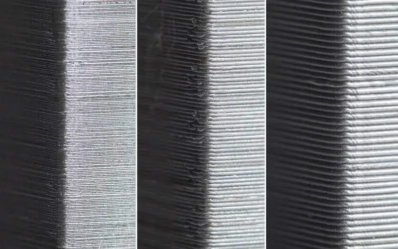
Generally, a layer height of 0.2 mm is a good compromise between cost, time and quality. For low-fidelity rapid prototypes, the increased layer height expedites the process.
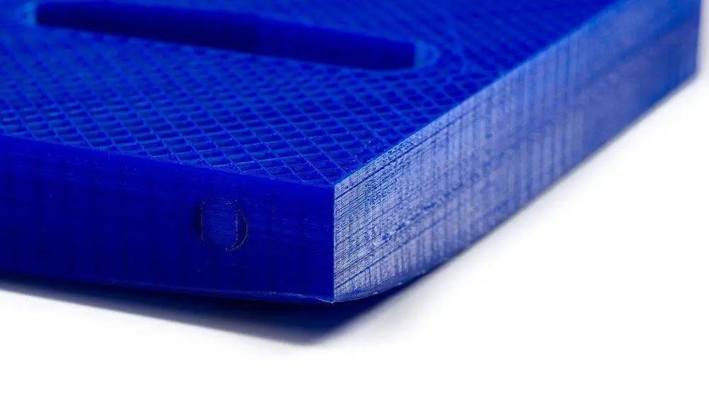
Layer Adhesion
For an FDM component, good adhesion between the deposited layers is critical. The molten thermoplastic is forced against the preceding layer as the nozzle extrudes the current. The high temperature and pressure re-melt the surface of the previous layer, allowing the new layer to connect with the previously printed portion. The binding strength between the multiple layers is always less than the material’s base strength.
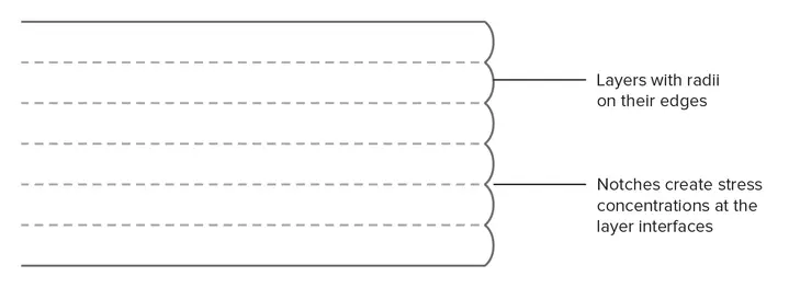
Hence FDM components are anisotropic by nature, and the strength in the Z-axis is always less than their strength in the XY plane. As a result, while designing components for FDM, keeping part orientation in mind is critical, especially for functional parts.
For example, the tensile strength of ABS with 50% infill in the X and Y direction is approximately four times more than in the Z direction. It also stretched about ten times more before breaking.
Furthermore, because the molten material is forced against the preceding layer, it deforms to an oval shape. Hence FDM items will always have a wavy surface, even at low layer height, and that minor features like small holes or threads may require post-processing after printing.
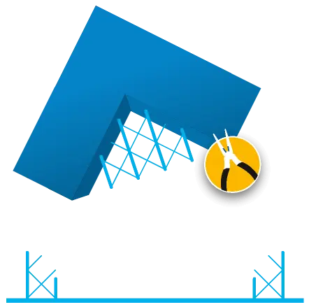
Support Structure
In FDM, geometries with overhangs will require a support structure. The molten thermoplastic cannot be deposited in the absence of air. As a result, some geometries necessitate support structures.
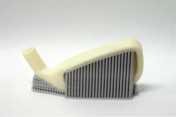
Surfaces printed on supports will have lesser surface quality than the remainder of the item. As a result, it is advised that the part be constructed to minimise the need for assistance.
Typically, support is printed using the same material as the print. In industrial printers, there are other support materials available that can dissolve in liquid. However, they are mostly utilized in high-end desktop or industrial FDM 3D printers. Printing on dissolvable supports enhances the surface quality of the item greatly but raises the total cost of a print due to the need for a dual-head FDM printer and the comparatively high cost of the dissolvable material.
Infill and Shell thickness
FDM pieces are typically not produced solid to save time and material. Instead, the exterior perimeter, known as the shell, is printed using numerous passes, and the inside with an internal, low-density structure, known as the infill.
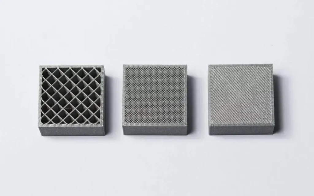
The infill and shell thickness of a print influences the strength of a component.
The default option for desktop FDM printers is 25% infill density and 1 mm shell thickness, a fair balance between strength and speed for rapid prints.
Warping
Warping is one of the most common FDM flaws. The dimensions of the extruded material shrink as it cools during solidification. Because various parts of the print cool at different rates, their dimensions also alter at varying rates. Differential cooling causes internal tensions to build up, pulling the bottom layer higher and causing it to distort.
Warping may be avoided by closely monitoring and controlling the temperature of the chamber and the build platform. Good adhesion between the component and the build platform also would help reduce the warping.
Fused deposition modeling advantages and disadvantages
Advantages of FDM
- FDM is the most cost-effective method of manufacturing bespoke thermoplastic components and prototypes.
- Due to the lower cost of FDM printers and wide availability, the lead times are minimal and cheaper than other additive manufacturing processes.
- There is a large variety of thermoplastic materials available for prototyping and certain non-commercial practicals. Most common injection moulding materials can be replicated using FDM
- The technology is aesthetically pleasing, easy to use, and appropriate for the workplace.
- Mechanical and environmental stability are provided by supported production-grade thermoplastics.
- FDM technology makes complex shapes and voids that would otherwise be impractical possible.
Disadvantages of FDM
- When compared to other 3D printing methods, FDM has the lowest dimensional accuracy and resolution, making it unsuitable for items with delicate features.
- Because FDM items are prone to noticeable layer lines, post-processing is essential for a smooth finish.
- Because of the layer adhesion technique, FDM components are inherently anisotropic.
Fused deposition modelling materials
The variety of materials accessible is one of FDM’s primary features. Commodity thermoplastics such as PLA and ABS to engineering materials such as PA, TPU, and PETG. For prototyping, there are high-performance thermoplastics such as PEEK and PEI during the embodiment stages of the new product design.
ABS
ABS-M30 is an excellent material for conceptual modelling, functional prototyping, production tools, and end-use parts. ABS-M30, up to 70% stronger than conventional FDM ABS, is perfect for production components, thermoforming tools, lightweight jigs and fixtures, and concept models. This thermoplastic has high tensile, impact, and flexural strength. Sparse or solid fill is available.
- Pros – Offers good strength, good temperature resistance
- Cons – More susceptible to warping
PC
PC (polycarbonate) is widely used in the automotive, aerospace, and medical industries, among many others. PC provides precision, durability, and stability, resulting in sturdy parts that resist functional testing. Rapid tooling, jigs and fixtures for production
- Pros – Accurate, Rigid, Stable, RF transparent, High tensile and flexural
- Cons – Not widely available, higher cost
PC-ABS
PC-ABS combines the best qualities of both PC and ABS materials, such as strong strength with the heat resistance of PC and the flexibility of ABS. PC-ABS composites are widely used in automotive, electronics, and telecommunications applications. Form fit and functional prototypes, low-volume production parts
- Pros – High impact strength, High heat resistance
- Cons -Not widely available, higher cost
PLA
PLA is a bioplastic and is one of the standard materials for this technology, along with ABS (Acrylonitrile Butadiene Styrene).
- Pros – Excellent visual quality, Easy to print with
- Cons- Low impact strength
Nylon
Nylon is one of the most widely used commercial FDM materials, and it possesses a good combination of tensile strength and toughness. Generally used for rapid prototyping concept validation models, prototype parts for visual design validation, and production toolings such as jigs, fixtures, and manufacturing aids. It can also be used for low-volume production parts with less demanding functional parts.
- Pros – High strength, Excellent wear, and chemical resistance
- Cons – Low humidity resistance
PETG
- Pros – Food safe although grooves and grannies of notches between the layers are a critical point for bacterial growth, good strength, easy to print
- Cons – Not widely available, higher cost
TPU
TPU 92A FDM Elastomer is a thermoplastic polyurethane substance used to make long-lasting elastomer components. The material allows for the development of high-functioning, long-lasting, and complicated parts with the anticipated material features of an elastomeric material, such as enhanced tear resistance, fatigue resistance, and memory recovery.
- Pros – Very flexible, good toughness, Durable, Abrasion resistance
- Cons – Difficult to print accurately
PEI
- Pros – Excellent strength-to-weight ratio, Excellent fire and chemical resistance
- Cons – High cost
Applications and uses of FDM
What may FDM 3D Printing be used for? Although the options for product creation and manufacture are limitless, the majority of applications fall into four broad categories:
- Functional prototypes
- Production and manufacturing tools
- Concept models
- Production quality parts
Fused Filament Fabrication (FFF) – Plastic Jet Printing
Similar to FDM, Fused Filament Fabrication is a term often used interchangeably. It’s a more open term for similar processes that utilise melted filament for layer-by-layer printing. This method is not limited by proprietary technologies.
Fused filament fabrication (FFF) is developed by the members of the RepRap project which is not restricted to use by others. You can read all about RepRap here. This is also referred to as Plastic Jet Printing.
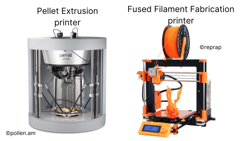
Pellet Extrusion
This technique involves using raw plastic pellets instead of filaments. In Pellet Extrusion, the pellets are melted and extruded through a nozzle to create the layers.
The most significant advantage of Pellet extrusion technology is its material availability. Pellets are the most widely available and used polymer format in the manufacturing industry. Hence, Pellet Extrusion benefits from an established supply chain with lower material costs.
How does Pellet Extrusion Work?
As the image shows, the extruder consists of an auger screw, extruder die, heating elements, and a material cartridge for the pellets. The process works very similar to an injection moulding machine in how it melts the pellets and pushes the molten plastic through the nozzle.
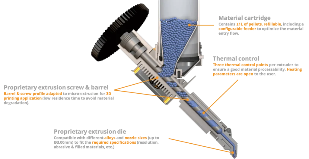
The printer head is then articulated by an XYX gantry system to print the parts as per the 3D model.
Composite Filament Fabrication (CFF)
What is Composite Filament Fabrication (CFF)?
Composite Filament Fabrication (CFF) adds continuous fibre strands such as carbon or fibreglass reinforcement to create composite, lightweight yet metal-like solid parts. CFF material extrusion technology, which uses two print nozzles, was introduced by Markfroged.
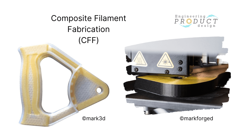
CFF is very similar to reinforced concrete with rebar. Like rebar reinforcement increases the strength of the brittle concrete, in CFF, the continuous fibre increases the strength of the part by increasing the strength.
| Fibreglass | Fiberglass is sturdy and comparably cost-effective and increases the part strength. |
| Carbon Fibre | Carbon Fibre is stiff and strong and behaves like aluminium alloy 6061. It is used for lightweight parts that carry medium to heavy loads. |
| Kevlar | Kevlar would make high-toughness and shock resistance parts, making it ideal for parts that undergo shock loading and are high-impact. It bends instead of breaking. |
| HSHT Fiberglass | High Strength High Temperature (HSHT) Fiberglass is a good candidate for high-temperature applications as it maintains strength and stiffness. This is because of its high heat-deflection property. |
How does Composite Filament Fabrication Work?
Composite Filament Fabrication printing steps
- The CFF process begins by extruding and depositing a thermoplastic layer, which forms the part’s infill and shells. This serves as the composites’ matrix material.
- Next, the continuous fibre is introduced into the matrix, which fuses with the thermoplastic using compatible resin coating.
- The above process is repeated layer by layer to create a composite structure with fibres as the backbone of the 3D-printed part.
Composite Filament Fabrication advantages
- High strength-to-weight ratio – Like conventional concrete and rebar, continuous fibres with thermoplastic materials create parts with exceptional strength-to-weight ratios, making them strong and lightweight.
- Design flexibility – Since fibres form the backbone, they can be laid out in specific orientations or patterns to optimise the part’s functionality.
- Part feature enhancement – Fibres can be placed in specific areas to increase localised strength per the part’s functionality.
Composite Filament Fabrication disadvantages
- Cost – As with any other 3D printing technology, initial equipment costs are high, which drives the manufacturing cost higher.
- Post-processing – Depending on the part design and final use, manufacturers might need post-processing techniques such as curing and heating.
Direct Ink Writing (DIW)
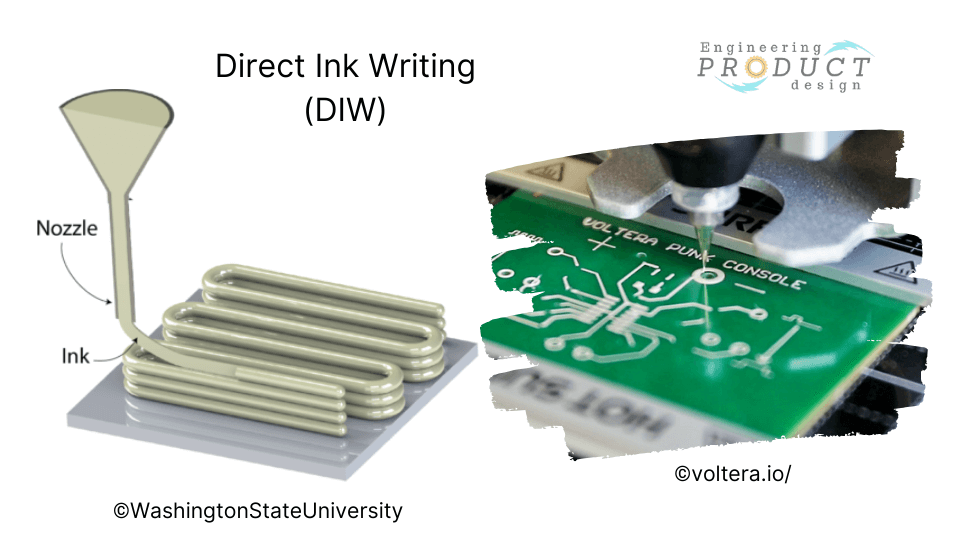
Direct Ink Writing (DIW)is another material extrusion technology variation predominantly employed at meso- and micro-scales. This method dispenses liquid-phase “ink” through tiny nozzles at controlled flow rates, depositing it along digitally defined paths to construct 3D structures layer-by-layer.
The DIW process can achieve very high material resolution, enabling the development of embedded circuitry and rapid manufacturing of sensors. Compared to traditional manufacturing, DIW eliminates masking and etching steps in electronic manufacturing.
Bound Metal Deposition (BMD)
BMD is a metal extrusion-based AM technology process where the metal powder-filled thermoplastic rods are extruded to create 3D parts. Instead of filament spools and pellets, bound metal rods, which are metal powders held together by either wax or polymer binders, are used. BMD is also known as Atomic Diffusion Additive Manufacturing (ADAM).
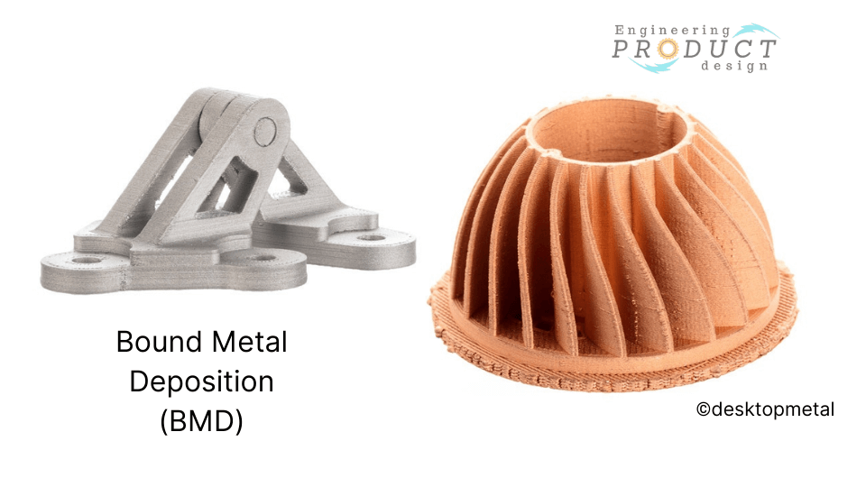
Desktop Metal’s patented process is called Bound Metal Deposition (BMD), while Markforged Inc. named their AM process Atomic Diffusion Additive Manufacturing (ADAM).
How does Bound Metal Deposition Work?
Step 1 – Material Preparation
- Feedstock: BMD uses a filament of metal powder bound in a polymer matrix. This filament is provided in spools and resembles the filament used in Fused Deposition Modeling (FDM), but it contains metal particles instead of just plastic.
- Polymer Binder: The polymer serves as a temporary binder to hold the metal particles together during printing.
Step 2 – Printing
- Extrusion: The filament is fed into a heated nozzle, which softens the polymer binder. This allows the material to be extruded layer by layer to form the desired shape.
- Layer Deposition: Each layer is laid down sequentially, fusing with the previous one to build the part according to the 3D model. The polymer binder holds the metal particles in place during this stage.
Step 3 – Debinding
- Binder Removal: After printing, the green part (the term for a part that has been printed but not yet sintered) undergoes a de-binding process to remove the polymer binder. This can be done using chemical solvents or thermal de-binding.
- Solvent Debinding: The part is immersed in a chemical bath that dissolves the polymer, leaving behind the loosely bound metal particles.
- Thermal Debinding: The part is heated in a furnace to burn off the binder. This step is carefully controlled to avoid damaging the part.
Step 4 – Sintering
- Furnace Treatment: The de-bound part (now a brown part) is placed in a high-temperature furnace. The metal particles fuse during sintering without melting entirely, resulting in a dense, solid metal part.
- Densification: The part shrinks as the spaces between the metal particles close. This step typically causes significant shrinkage, which is predictable and accounted for in the design phase.
What Is the Difference Between Material Jetting and Material Extrusion?
Material jetting and Material extrusion are two different 3D printing technologies that differ in their processes and mechanisms.
Material Jetting operates similarly to inkjet printing. It involves jetting tiny droplets of photopolymer materials onto a build platform. These droplets are often cured with UV light to solidify and form layers. This process is repeated layer by layer until the object is fully printed.
Material extrusion involves the deposition of molten thermoplastic filament through a heated nozzle onto a build platform. The nozzle moves according to the design specifications, laying down layers of material that fuse together upon cooling to form the final object.
| Property | Material Jetting | Material Extrusion |
|---|---|---|
| Material | photopolymers or resins that solidify under UV light are used in material jetting. These materials can produce high-resolution prints with fine details and smooth surface finishes. | A wide range of thermoplastics, such as PLA, ABS, PETG, and more, can be used in material extrusion. The choice of material affects properties like the final print’s strength, flexibility, and temperature resistance. |
| Accuracy & Resolution | Material jetting offers high resolution and accuracy, making it suitable for applications requiring intricate details and precise dimensions. | While material extrusion can produce detailed prints, its resolution might be lower than that of material jetting. Layer lines might be more visible, affecting the surface finish. |
| Post-processing | Often, parts produced by material jetting may require additional post-curing to achieve optimal mechanical properties and surface finish. | Parts printed through material extrusion often require less post-processing. However, smoothing techniques or additional treatments might be applied to improve surface quality. |
Recommended reference
Diegel, Olaf, et al. A Practical Guide to Design for Additive Manufacturing. Springer Nature Singapore, 2019.
Celik, Emrah. Additive Manufacturing: Science and Technology. Walter de Gruyter GmbH, 2020.
Stratasys. Stratasys – Industrial 3D Printing Manufacturers, https://www.stratasys.com/en/Desktop Metal. Desktop Metal. Define the future. Make it real. | Desktop Metal, https://www.desktopmetal.com/.