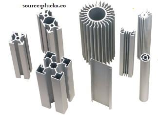
In Metal extrusion, a cylindrical billet inside a closed cavity is forced to flow through a die with a fixed cross-sectional profile.
Contents covered in this article

What is Metal Extrusion?
Metal Extrusion is a metal-forming manufacturing process in which a cylindrical billet inside a closed cavity is forced to flow through a die of the desired cross-section. These fixed cross-sectional profile extruded parts are called “Extrudates” and are pushed out using either a mechanical or hydraulic press. The process, patented by Joseph Bramah, was first used to extrude lead pipes by Thomas Burr.
The most commonly extruded materials are Aluminium, Copper, Steel, Magnesium, and Lead. Plastics and ceramics are also extruded extensively but not discussed in this article.
Characteristics of metal extrusion
- Able to create complex cross-sections and will be uniform over the entire length of the extrudates
- Factors that affect the quality of extrusion are die design, extrusion ratio, billet temperature, lubrication, and extrusion speed. Check out the detailed design guide for metal extrusion, “How to design parts for direct metal extrusion”, to understand the 5 key design variables of metal extrusion and design for manufacture (DFM) extrusion design tips.
- Like any other metal-forming process, it can be either hot or cold. However, the process is generally carried out at elevated temperatures to reduce the extrusion force and improve the material’s ductility.
- Low cost due to reduced raw material wastage and high production rate
- Brittle material can be deformed without a tear as it only exerts compressive and shear forces in the stock part
- Parts that are formed have an excellent surface finish which minimizes post-processing machining
- Metal extrusion tends to produce a favourable elongated grain structure in the direction of the material.
- The minimum wall thickness of ~1mm (aluminium) to ~3mm (steel) could be achieved.
Metal extrusion types
Metal extrusion can be subdivided and grouped into the following categories depending on the direction of extrusion flow, and the medium used to apply force.
They can also be classified depending on the working temperature
- Hot extrusion
- Cold Extrusion
The table below highlights each metal extrusion technique’s main advantages and disadvantages, providing a comprehensive overview of its strengths and limitations.
| Extrusion Technique | Pros | Cons |
|---|---|---|
| Direct Extrusion | – Simple and versatile process – Suitable for a wide range of materials and cross-sectional shapes – High production rates possible | – Higher friction between billet and container, leading to higher extrusion force required – Greater wear on the die and container |
| Indirect Extrusion | Lower friction as the billet does not move relative to the container | Limited to smaller cross-sections |
| Lower extrusion force required | More complex tooling required | |
| Less wear on the die and container | ||
| Hydrostatic Extrusion | Uniform material flow due to pressurised fluid | Requires special equipment and high-pressure fluid systems |
| Can extrude brittle materials without cracking | Higher operational costs | |
| Lower friction and extrusion force required | ||
| Lateral or side Extrusion | Produces complex cross-sections | Limited to specific shapes and applications |
| Efficient material usage | It may require more complex machinery | |
| Hot Extrusion | Easier to extrude metals with high deformation resistance | Requires heating equipment and energy-intensive process |
| Can produce larger and more complex shapes | Possible oxidation and surface defects due to high temperatures | |
| Higher production speeds | ||
| Cold Extrusion | Improved mechanical properties due to work hardening | Higher extrusion forces required compared to hot extrusion |
| Better surface finish and dimensional accuracy | Limited to materials with good cold formability | |
| No need for heating, saving energy | ||
| Impact Extrusion | High production rates and suitable for mass production | Limited to small, hollow shapes |
| Good surface finish and dimensional accuracy | Tooling can be expensive and complex. | |
| Efficient material usage with minimal waste |
Direct Extrusion
Direct Extrusion, sometimes called Forward Extrusion, is the most common type of extrusion. As shown in the figure below, the process begins by loading a heated billet (only for hot extrusion, discussed later) into a press cavity container where a dummy block is placed behind it. Then the mechanical or hydraulic ram presses on the material to push it out through the die. Then, while still hot, the part is stretched to straighten. This process is beautifully animated by Core Materials.
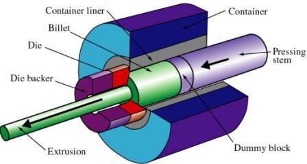
Under direct extrusion, the high friction caused by steels at higher temperatures is reduced using molten glass as a lubricant while oils with graphite powder are used for lubrication for low temperatures. The dummy block protects the tip of the pressing stem (punch or ram) in hot extrusion. When the punch reaches the end of its stroke, a small portion of the billet called the “butt end” cannot be pushed through the die opening.
Direct metal extrusion advantages
- No billet modification required
- It can be used for both hot and cold extrusion.
- Simple tooling compared to other extrusion processes
Direct metal extrusion disadvantages
- High force requirement due to friction
- The butt end left inside the cavity
- The force required to push the ram changes as the punch moves
Indirect Extrusion
In Indirect Extrusion, the die is located at the end of the hydraulic ram and moves towards the billet inside the cavity to push the material through the die. This is illustrated in figure 2 below.
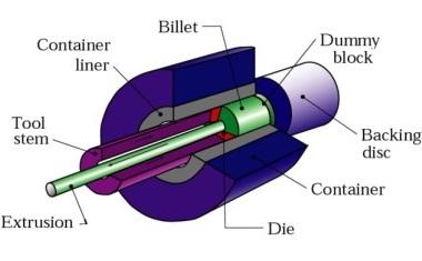
This process consumes less power due to the static billet container causing less friction on the billet. However, supporting the extruded part is difficult when the extrudate exits the die.
In-direct metal extrusion advantages
- Less friction and less power used
- It can be used for both hot and cold extrusion
- Simple tooling compared to other extrusion processes
In-direct metal extrusion disadvantages
- Difficult to support the extruded part
- The hollow ram limits the load applied
Hydrostatic extrusion
In hydrostatic extrusion, the chamber/ cavity is smaller than the billet and filled with hydraulic fluid, which transfers the force from the ram to the billet, as shown in figure 3. Although tri-axial forces are applied by the fluid, the pressure improves billet formability on the billet. Sealing the fluid must be considered early to avoid any leaking and reduce pressure issues.
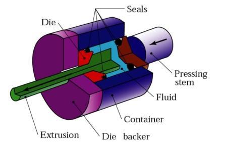
Although the hydraulic fluid eliminates the friction between the wall and the billet by isolating them, due to the specialised equipment requirement, the high set-up time and low production rate limit its usage in the industry compared to other extrusion processes.
Hydrostatic metal extrusion advantages
- Low power/force requirement due to no friction
- Fast production rates & high reduction ratios
- Lower billet temperature
- Even the flow of material due to the balanced force distribution
- Large billets and large cross-sections can be extruded
- No billet residue is left in the container
Hydrostatic metal extrusion disadvantages
- Billets need to be prepared by tapering one end to match the die entry angle.
- Only cold extrusion is possible
- Difficult to contain the high-pressure fluid
Lateral Extrusion
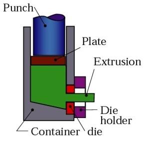
In Lateral Extrusion, the container is in a vertical position, as shown in the image, and the die is on the side. This process is suitable for low melting point material.
Impact Extrusion
Impact extrusion is part of the cold extrusion category, very similar to In-direct extrusion and limited to softer metals such as Lead, Aluminium and copper. As the schematic illustrates, the punch is pushed down at high speed and has extreme force on the slug to extrude backwards. The thickness of the Extrude is a function of the clearance between the punch and the die cavity. The Extrudates are slid off the punch using a stripper plate.
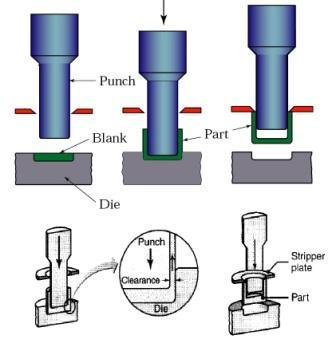
For impact extrusions, a mechanical press is often used, and the part is formed at high speed and over a relatively short stroke
Since the forces acting on the punch and die extremely high, tooling must have sufficient impact resistance, fatigue resistance and strength for extruding metal by the impact. Impact extrusion can be divided into the following three types by material flow.
- Forward
- Reverse
- Combination
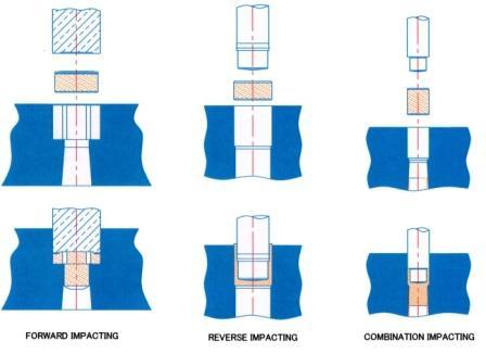
In forward impact extrusion, the metal flows in the same direction that the force is delivered, while it flows in the opposite direction in reverse impact extrusion. As the image shows above, the metal flows in both directions in combination.
Impact metal extrusion advantages
- Raw material savings of up to 90%
- Reduced machining times by up to 75%
- Elimination of secondary machining operations
- Reduction in multi-part assemblies
- Improved mechanical properties for material strength and machining due to the cold working of the material
- Significantly reduced total part costs by up to 50%
- Hollow thin-walled tubes, closed on one end, are often produced in the manufacturing industry by backward impact extrusion.
Impact metal extrusion disadvantages
- Produced as long as the part is symmetrical over the axis by which it is formed
- Many of the parts formed by impacting in industry, will require further manufacturing processes, such as metal forging, ironing or machining, before completion.
Metal Extrusion Applications
Here’s a tabulation of example application products and materials made from various metal extrusion techniques:
| Extrusion Technique | Example Application Products | Materials Used |
|---|---|---|
| Direct Extrusion | Pipes, rods, aluminium window frames, structural components | Aluminium, copper, magnesium, steel, titanium |
| Indirect Extrusion | Seamless tubing, solid and hollow shapes, electrical wire insulation | Aluminium, copper, magnesium, steel |
| Hydrostatic Extrusion | High-strength steel rods, stainless steel wire, metal matrix composites | High-strength steel, stainless steel, copper, titanium |
| Lateral or Vertical Extrusion | T-shaped or H-shaped profiles, complex cross-sections for automotive parts | Aluminium, copper, magnesium, steel |
| Hot Extrusion | Automotive parts, aerospace components, large structural components | Aluminium, copper, magnesium, steel, titanium |
| Cold Extrusion | Fasteners (bolts, nuts), automotive components (gears, shafts), bicycle parts | Aluminium, copper, steel, lead |
| Impact Extrusion | Aluminium beverage cans, battery cases, small containers, collapsible tubes | Aluminium, tin, lead, zinc |
This table summarises the main products and materials of each extrusion technique, highlighting each method’s versatility and specific applications in various industries.
Metal Extrusion materials
Tabulated summary of the metals that can be extruded, along with their properties and common applications:
| Metal | Properties | Common Applications |
| Aluminium | Excellent malleability, low density, corrosion-resistant | Window frames, automotive parts, structural components, heat sinks |
| Copper | Excellent electrical and thermal conductivity | Electrical wiring, plumbing tubes, heat exchangers, decorative items |
| Magnesium | Lightweight, good strength-to-weight ratio | Automotive parts, aerospace components, electronics housings |
| Lead | Highly malleable, corrosion-resistant | Battery grids, shielding for cables, radiation protection |
| Tin | Soft, malleable | Food containers, battery components, coating for other metals |
| Zinc | Corrosion-resistant, low melting point | Automotive parts, hardware, protective coatings (galvanisation) |
| Steel | Strong, durable, various grades available | Structural components, pipes, rails, machinery parts |
| Stainless Steel | Corrosion-resistant, strong | Medical devices, food processing equipment, architectural components |
| Titanium | Strong, lightweight, corrosion-resistant | Aerospace components, medical implants, sports equipment |
| Nickel and Alloys | High-temperature and corrosion resistance | Aerospace components, chemical processing equipment, high-temperature applications |
| Brass (Cu-Zn Alloy) | Good machinability, corrosion-resistant | Plumbing fittings, musical instruments, decorative items |
| Bronze (Cu-Sn Alloy) | Durable, wear-resistant, corrosion-resistant | Bearings, bushings, marine hardware |
| Alloy Steels | Customised properties (e.g., added chromium, vanadium, molybdenum) | High-strength components, tools, heavy machinery parts |
| Inconel (Ni-Cr Alloy) | High-temperature strength, oxidation-resistant | Jet engines, gas turbines, heat exchangers |
Extrusion Defects
Depending on the material condition and process variables, extrudates can develop many defects that could affect the quality of the end product. These defects can be grouped under the following three defects.
- Surface cracking
- Piping
- Internal cracking
Surface Cracking
Surface cracking, also known as “extrusion cracks” or “surface checking,” occurs when the surface of the extruded material fractures during the extrusion process. This defect can arise due to several factors:
- Excessive Extrusion Speed: High extrusion speeds can cause the surface temperature to rise excessively, leading to cracking.
- Material Properties: Materials with low ductility, impurities, or inclusions are more prone to surface cracking.
- Die Design: Poor die design that causes uneven stress distribution can also contribute to surface cracking.
- Temperature Control: Improper temperature control, either too high or too low, can lead to differential expansion and contraction, causing cracks on the surface.
Surface cracks compromise the extruded product’s aesthetic quality and weaken its structural integrity, making it unsuitable for critical applications.
Piping
Piping, also known as “extrusion pip” or “central burst,” is a defect characterised by the formation of a central void or cavity along the length of the extruded product. This defect is typically caused by:
- Non-uniform Material Flow: When the material flow is uneven, it can cause a vacuum or low-pressure area in the centre, forming a pipe.
- Improper Billet Temperature: If the billet temperature is not uniform, it can lead to differential flow rates, causing central voids.
- Inadequate Die Design: A die that does not ensure balanced material flow can contribute to the formation of central cavities.
- High Friction: Excessive friction between the billet and the container can cause the material to flow unevenly, leading to piping.
Piping can severely affect the mechanical properties of the extruded product, making it unsuitable for applications where structural integrity is crucial.
Internal Cracking
Internal cracking, also known as “chevron cracking” or “centre cracking,” occurs within the body of the extruded material and is not visible on the surface. This defect is caused by:
- High Extrusion Ratio: High reduction ratios can cause internal stresses that lead to cracking.
- Material Properties: Materials that are not sufficiently ductile or have inclusions and impurities are more susceptible to internal cracking.
- Temperature Variations: Inconsistent temperature within the billet can lead to differential flow rates, causing internal stress and cracks.
- Improper Lubrication: Lack of adequate lubrication can increase friction, leading to internal stress and eventual cracking.
Internal cracks compromise the structural integrity and durability of the extruded product, often leading to failure under mechanical stress or during subsequent processing.
Understanding and controlling these defects are critical for ensuring the quality and performance of extruded products. Proper material selection, precise control of process parameters, and optimised die design are essential strategies for minimising these defects and producing high-quality extrudates.
Direct metal extrusion design guide – DFM
Shape, alloy, tolerance, surface polish, and CCD are essential design elements to consider while designing metal extrusion parts.
A thoughtfully designed metal extrusion part will successfully satisfy the final product design’s form, fit and function. Following is a detailed design guide for metal extrusion, which explores 5 key design variables of metal extrusion and provides design for manufacture (DFM) extrusion design tips.
What is direct metal extrusion?
Direct metal extrusion is one of 5 main types of metal extrusion processes in which a metal billet is forced through a fixed die to create a specified shape.
This metal-forming process can be performed both hot and cold. But generally, the billets are heated up before pushing through the die to reduce friction and the force required. The dimensions of the extruded workpiece depend on the extruded profile and the amount of material that the workpiece withholds. The parts obtained after extrusion is called extrudates.
Direct extrusion is the most common extrusion process used in profile extrusion, mainly due to its simplicity in the manufacturing design and flexibility in profile manufacturing.
The common metals used for extrusion are steel, copper and aluminium. Aluminium alloy extrusion has many advantages, such as being lightweight, having a high strength-to-weight ratio, corrosion-resistant, heat conductive, fully recyclable, having very tight tolerances, easy to fabricate and being cost-effective. Hence, it is one of the most commonly extruded materials.
For the above reason, this article will be biased towards aluminium alloy extrusions.
Metal extrusion design factors
Making the right design choices will yield significant benefits in terms of extrudability, manufacturing cost and design. During the early embodiment design phase of the part, the following five design variables of metal extrusion should be considered before moving on to the detailed design.
Alloys and their tempers
Pure aluminium, like many other metals, has its limitations. Hence they are alloyed with elements such as copper, and magnesium, to produce alloys with different properties. Different aluminium alloys have different properties and characteristics, hence offering different benefits. Depending on the final product design requirements, choices must be made regarding its mechanical performance, post-processing, quality, and cost to achieve the desired functional part.
- Mechanical performance
- Product properties – strength, ductility
- Workability – extrudability, product yield
- Heat treatable or non-heat-treatable
- Heat treatable – 2xxx, 6xxx, 7xxx (HT)
- Heat treatable – 1xxx, 3xxx, 5xxx (NHT)
- Corrosion characteristics
- Alloy composition
- Cost
Further, depending on the composition of the chosen alloy, it can be strengthened and hardened using various tempering techniques.
Golden tip – 6000 series aluminium alloys are the most common and selected for almost 75% of the aluminium extrusion. 6063 and 6061 are the most frequently used.
This publication from Aluminium Extruders Council has more information on aluminium alloys, their properties and performance parameters on commonly used aluminium extrusion alloys.
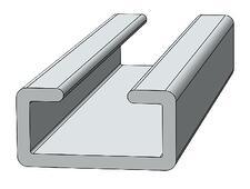
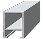
Shapes (Extrusion profile)
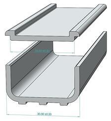
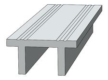
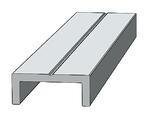
The aluminium extrusion shape configurations can be grouped into three categories. Hollow, semi-hollow and solid as shown in figure 2.
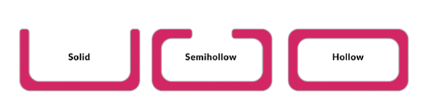
Solid profiles are cheaper to make as they are the least complex. Semi-hollow profiles are defined by the tongue ratio.
The following should be considered when considering the shape configuration
- Uniform wall thickness
- Symmetry
- Rounded edges
- Shape constraints
Golden tip – The least complex and easier to extrude a profile, is lower the cost, than a profile that is more complex and has a longer process.
Tolerances
Most of the time, the extrusion profiles will be part of an assembly and need close interfacing with surrounding components. Hence dimensional tolerancing becomes critical. The product designer should be aware of the ISO standards’ dimensional tolerancing to which extrusion parts can be cost-effectively made. These should cover straightness, flatness, twist, thickness, angles, contours and corner radii.
The following Aluminium association’s standard tolerance tables provide key Aluminium extrusion dimensional tolerances:
- Length, Straightness, Twist, Flatness, Surface roughness – Wire, Rod, Bar and Profiles
- Round tube – Diameter, Width and Depth of Square, rectangular, Hexagonal and octagonal tube, wall thickness
The following videos from the Aluminium association on how aluminium extrusion tolerances can be accurately measured give you an understanding of what is measured and how to use the above tables.
- How to inspect metal and space dimensions on solid profiles
- How to inspect metal and space dimensions on hollow profiles
- How to inspect the straightness of metal extrusion
- How to inspect the twist of metal extrusion
- How to inspect the flatness of metal extrusion
Surface Finish
When aluminium is extruded, a thin oxide layer forms on its surface to protect it from the atmosphere. Different surface finishes and treatments are performed to increase or enhance the protection on the product. These include:
- Powder coating (use of solvents)
- Liquid coating (use of paints)
- Anodizing (electrochemical process)
- Chemical finish (e.g. etching, etc.)
- Mechanical finish (e.g. polishing, sanding, etc.)
- Pre-treatment (e.g. cleaning, etc.)
Circumscribing Circle Diameter (CCD)
Circumscribing circle diameter is a common measurement of a metal extrusion profile and is the smallest circle that encloses the entire extrusion cross-section. Although it is possible to produce extrusions up to 18” CCD, the cost increases with increasing CCD. Hence, most common extrusions are less than 8” in diameter.
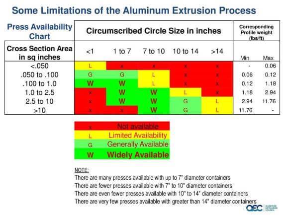
Golden tip – Keep the design so that the profile CCDs are under 8” and the Wt/Ft is 3 lbs or less which would improve the design significantly.
DFM guidelines for metal extrusions
Design for manufacture is about integrating the design with the practicality of manufacturing the part. The goal is to design an extrusion profile that is easily and economically manufactured, which satisfies the part’s form, fit and function.
Design with a suitable wall thickness
It is common for the metal to distort during the extrusion process due to thin or unsymmetrical metal thickness, similar to metal casting processes such as sand and investment casting. Specifying a suitable metal thickness that avoids distortion, depending on the structural needs to satisfy the requirements and make it cost-effective is essential.
The following factors dictate the minimal wall thickness (link) and need careful consideration during the design stages of the new product development.
- Heat generation – Larger the extrusion thickness, the more it generates heat during the process, which would distort the profile.
- Tolerances
- Alloy choice
- Cross-sectional complexity
The following reference chart shows the minimum wall thicknesses practical from an extrusion standpoint based on the profile’s circumscribing circle diameter.
Table 1 Minimum wall thickness vs CCD
| Circumscribing Circle (inches) | Class 1 Solids & Semi hollows (inches) | Class 2 Hollows (inches) |
|---|---|---|
| 0.5 ≤ CCD < 2 | 0.04 | 0.055 |
| 2 ≤ CCD < 3 | 0.045 | 0.062 |
| 3 ≤ CCD < 4 | 0.05 | 0.078 |
| 4 ≤ CCD < 5 | 0.062 | 0.094 |
| 5 ≤ CCD < 6 | 0.078 | 0.11 |
| 6 ≤ CCD < 7 | 0.094 | 0.125 |
| 7 ≤ CCD < 8 | 0.11 | 0.14 |
| 8 ≤ CCD < 9 | 0.125 | 0.156 |
| 9 ≤ CCD < 10 | 0.14 | 0.188 |
| 10 ≤ CCD < 11 | 0.156 | 0.204 |
| 11 ≤ CCD < 12 | 0.172 | 0.22 |
| 12 ≤ CCD < 13 | 0.188 | 0.236 |
Design with uniform metal thickness
One of the advantages of extrusion is that it allows putting extra material where needed, such as mounting hole locations & high-stress areas, and elsewhere, you could have thinner sections. But, the adjacent wall thickness change must be less than 2:1.
Large non-uniform metal thickness variations would introduce dimensional control problems. So, it is crucial to maintain a uniform metal thickness throughout the process if possible. In case of a difference in thickness, ensure there are streamlined transitions in areas with a sharp change in thickness.
Use metal dimensions when tolerancing
Dimensions across solid profile metal are easier to measure compared to open gaps, hence easier to make it to a tight tolerance. These are called “metal dimensions”, and the designer should specify and rely on these as much as possible for tighter interfacing sections of the aluminium extrusion.
Golden tip – A metal dimension can be extruded to close tolerance while open space dimension is more difficult to hold to close tolerances.
The DIN ISO 2768-1 tolerance standards can be used for aluminium extrusion as most extrusion manufacturers work to these standards.
Consider surface finishes
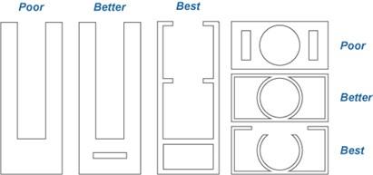
Sudden changes in wall thickness and inside profile junctions such as webs, flanges and ribs create visual stripes on the opposite side of the wall. These can be smoothed out by breaking the surface with grooves and serrations.
Adding appropriate corner radii also minimises the sink on the outside.
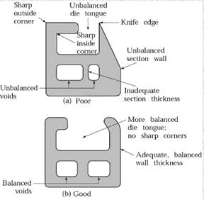
Remove sharp edges
Edges of the profile openings should be rounded to avoid the die tongue snapping off. This will also aid material flow and make it easier to extrude.
The following corner radii are recommended for corner design:
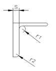
| Wall thickness mm (inch) | Recommended corner radius mm (inch) | ||
|---|---|---|---|
| Over | Up to | R1 | R2 |
| 0 | 2 ( 0.08″) | 2 (0.08″) | 1 (0.04″) |
| 2 ( 0.08″) | 4 (0.16″) | 2.5 (0.1″) | 1.6 (0.06″) |
| 4 (0.16″) | 6 (0.24″) | 4 (0.16″) | 2 (0.08″) |
| 6 (0.24″) | 10 (0.39″) | 6 (0.24″) | 3 (0.12″) |
| 10 (0.39″) | 20 (0.79″) | 10 (0.39″) | 5 (0.20″) |
| 20 (0.79″) | 35 (1.38″) | 16 (0.63″) | 10 (0.39″) |
| 35 (1.38″) | 50 (2″) | 20 (0.79″) | 16 (0.63″) |
Source: Purso
Introduce smooth transitions
As discussed before, areas that involve changes in thickness from thick to thin should be streamlined over a curved radius with smooth transitions to avoid problems related to dimensional control.
Incorporate webs
The hollow portions in a design can be extruded easily, using a web that makes extrusion of thin wall sections without any problem.
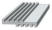
Incorporate ribs
Ribs are used in designs because they help reduce the twisting in broad, thin sections and make them flat or straight.
Incorporate indexing mark
Incorporating indexing marks can help distinguish between inside and outside surfaces or differentiate between similar profiles. They can also be used as scribe lines for drilling and tapping, assembly alignment lines, etc., during the final assembly.
Consider post-processing
When the final design specification of the extrusion profile is known, ensure any post-processing details are considered or shared with the profile designer. For example, very similar to sand casting design, where any close interface machining surfaces would need additional wall thickness.
- Working allowances for machined surfaces need to be added and incorporated into the extrusion.
- Dimensioning of screw pockets and functional areas taking profile tolerances into account
- Interfaces between profile and machining standards
- Surface treatments: before/after (for example, certain features such as threads might need masking before painting or anodising)
- The dimensioning of bent components cannot fully comply with the most common machining standards
Aluminium Extrusion
What is Aluminium Extrusion?
Aluminium extrusion is a process in which aluminum alloy material is forced through a die with a specific cross-sectional profile. By pushing the aluminum billet through the die using high pressure, it takes on the shape of the die opening. This technique allows for the creation of complex and precise shapes that can be used in various applications across different industries. The extrusion process can be performed hot or cold, depending on the properties desired in the final product.

Aluminium Extrusion Uses
Aluminium extrusions are versatile and find applications in numerous industries due to their lightweight, strength, and corrosion resistance. The key uses of aluminum extrusions include:
- Construction: Window frames, doors, curtain walls, and structural components.
- Transportation: Automotive parts, aircraft components, rail profiles, and marine structures.
- Electrical: Heat sinks, enclosures for electronic devices, and busbars.
- Consumer Goods: Furniture, sporting goods, and appliances.
- Industrial Applications: Machinery components, pipes, and profiles for manufacturing processes.
What are Aluminium Extrusions Used For?
Aluminium extrusions are used to create a wide range of products due to their adaptability and performance characteristics. They are used for:
- Architectural Frameworks: Providing structural integrity and aesthetic appeal to buildings.
- Automotive Components: Offering lightweight yet strong solutions for vehicle parts to improve fuel efficiency.
- Heat Management: Serving as heat sinks in electronic devices to dissipate heat effectively.
- Structural Applications: Used in scaffolding, bridges, and other structural supports due to their high strength-to-weight ratio.
- Consumer Products: Forming parts of household appliances, furniture, and recreational equipment.
How Does Aluminium Extrusion Work?
The aluminium extrusion process involves several steps:
- Heating the Billet: The aluminium billet is heated to a temperature where it becomes malleable but not molten.
- Loading the Billet: The heated billet is loaded into the extrusion press.
- Extrusion: The billet is forced through a die by a hydraulic ram. As the billet is pushed through the die, it takes on the shape of the die’s cross-sectional profile.
- Cooling: The extruded profile is cooled using air or water.
- Cutting: The extruded length is cut to the desired size.
- Finishing: The extruded product may be treated with additional finishing processes, such as anodising, painting, or machining.
Types of Aluminium Extrusions
Aluminium extrusions come in various types based on their shape and intended use:
- Solid Extrusions: These have no voids or openings and include shapes like rods, beams, and angles.
- Hollow Extrusions: These have one or more voids and include shapes like tubes and rectangular profiles.
- Semi-Hollow Extrusions: These have partially enclosed voids and include shapes that combine features of both solid and hollow extrusions.
Advantages of Aluminium Extrusion Compared to Solid Aluminium and Steel Extrusion
- Weight: Aluminium extrusions are significantly lighter than steel, which is beneficial for applications requiring easy handling and transportation.
- Corrosion Resistance: Aluminium naturally forms a protective oxide layer, making it highly resistant to corrosion, unlike steel which can rust without protective coatings.
- Versatility: Aluminium can be extruded into complex shapes with tight tolerances, making it suitable for a wide range of applications.
- Thermal Conductivity: Aluminium has excellent thermal conductivity, making it ideal for heat sinks and other heat-dissipation applications.
- Cost-Effectiveness: While the initial cost of aluminium extrusion dies can be high, the overall process is cost-effective for high-volume production runs.
Aluminium Alloy Grades Used in Extrusions
Various aluminium alloy grades are used in extrusion, each offering unique properties:
- 6061: Known for its good mechanical properties and weldability, making it ideal for structural applications.
- 6063: Often referred to as the architectural alloy, it is used for window frames, irrigation tubing, and other architectural applications due to its excellent surface finish and corrosion resistance.
- 3003: Known for its excellent corrosion resistance and moderate strength, making it suitable for chemical equipment and storage tanks.
- 7075: One of the highest-strength aluminium alloys, used in aerospace applications where high strength-to-weight ratios are critical.
- 2024: Offers high strength and good fatigue resistance, commonly used in aerospace components.
Aluminium extrusion is a highly efficient and versatile manufacturing process that enables the production of complex and lightweight profiles for a wide range of applications, making it a preferred choice in many industries.
References and recommended reading
- Kalpakjian, S., & Schmid, S. R. (2009). Manufacturing Engineering & Technology (Sixth edition ed.). London: Pearson.
- Extrusion. (n.d.). efunda. Retrieved October 2017, from http://www.efunda.com/processes/metal_processing/extrusion.cfm.
- Extrusion. (n.d.). Engineers Edge. Retrieved October 2017, from https://www.engineersedge.com/extrusion.htm.
- Extrusion. (n.d.). Engineers Handbook. Retrieved October 2017, from http://www.engineershandbook.com/MfgMethods/extrusion.htm.
- Extrusion. (n.d.). The Library of Manufacturing. Retrieved October 2017, from http://thelibraryofmanufacturing.com/extrusion.html.
- Extrusion. (n.d.). Wikipedia. Retrieved October 2017, from https://en.wikipedia.org/wiki/Extrusion.