The importance of advanced machining processes in modern manufacturing cannot be overstated. They offer several advantages over conventional machining methods
What are Advanced Machining Processes?
Advanced machining processes are cutting-edge techniques used to shape, cut, or remove material from a workpiece to achieve the desired geometry and surface finish. Unlike traditional methods such as turning, milling, or drilling, advanced processes leverage novel mechanisms like electrical, chemical, and thermal energy to machine metals and other hard-to-cut materials. These processes are critical in manufacturing industries where precision, speed, and the ability to handle complex geometries and tough materials are paramount.
Contents covered in this article
Types of Advanced Machining Processes
This article explores several key advanced machining processes, each with its unique principles, advantages, and applications:
- Electrical Discharge Machining (EDM) – EDM uses electrical sparks to erode material, making it ideal for hard metals and complex shapes.
- Plasma Cutting – It employs a high-velocity jet of ionised gas to cut conductive materials. It is known for its speed and ability to cut thick sections.
- Laser Beam Machining (Laser Cutting) – Uses focused laser beams to melt, burn, or vaporise material, offering high precision and minimal heat-affected zones.
- Waterjet Cutting Machining – It utilises a high-pressure stream of water, often with an abrasive, to cut materials without generating heat, suitable for various materials, including metals, stone, and composites.
- Electrochemical Machining (ECM) – ECM removes material through anodic dissolution, effective for high-precision and stress-free machining of tough alloys.
- Thermal Energy Processes – These encompasses techniques such as electron beam machining (EBM) and ion beam machining (IBM) that use focused thermal energy for cutting and shaping.
- Chemical Machining – These Chemical machining Involves the selective removal of material using chemical etchants, which are useful for creating intricate and precise components without mechanical forces.
Electrical Discharge Machining (EDM)
Electrical Discharge Machining uses electrical spark discharges to shape and form metal components by erosion.
What is Electrical Discharge Machining
Electrical Discharge Machining (EDM) is a manufacturing process that shapes and forms metal parts using electrical discharges or sparks to remove material from a workpiece made of conductive material. EDM is sometimes known as electro-discharge or spark-erosion machining.
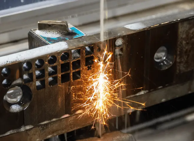
The process occurs in a dielectric fluid, which acts as an insulator, a cooling medium, and a flushing medium.
EDM is commonly used to produce intricate shapes or features that are difficult or impossible to create with traditional methods. Also, several industries prefer it for cutting hardened materials. Examples include:
- Making dies for forging, extrusion, die casting, injection moulding
- Machining small deep holes – uses tungsten wire as an electrode
- Very narrow slots in parts
- Cooling holes in turbine blades
EDM is a high-precision method that can remove approximately 10-6 to 10-4 mm ( of material per spark discharge and produce parts with extremely tight tolerances, thin walls, and small features. Also, EDM results in a high-quality surface finish, sometimes even mirror-like, thus requiring reduced post-processing.
Various industries apply this manufacturing process, including but not limited to:
- Aerospace
- Medical
- Automotive
How does Electrical Discharge Machining work?
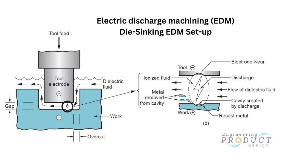
EDM consists of a machining tool known as the electrode, the workpiece, a DC power supply, and a dielectric fluid.
Tool and workpiece preparation
The process requires two following initial steps. One is the connection of the electrode and the workpiece to the DC power supply. The second is ensuring the dielectric fluid covers the electrode and workpiece completely.
Material removal
Then, the machine feeds the tool electrode. When the tool electrode is close enough to the workpiece, it generates a potential difference that is high enough to break the dielectric down and create a discharge that results in a cavity on the workpiece. Then, the dielectric fluid flow removes the material from the cavity.
The process involves repeated discharges, typically at a 200 to 500 KHz frequency, with voltages of 50 to 380 V and currents of 0.1 to 500 A.
The material of the workpiece must be electrically conductive, with the material’s melting point and latent heat of melting as the properties that will determine the amount of material removed per discharge.
The most popular electrodes for EDM are graphite electrodes. However, it is essential to highlight that electrodes made of brass, copper, and copper-tungsten alloys are also available.
Type of EDM
There are four types of EDM. These are:
Sinker or die-sinking EDM
Die-sinking EDM is considered the first type of EDM that ever existed. Sinker EDM uses an electrode that mirrors the shape wanted on the workpiece, similar to a stamping die. Therefore, it can achieve the required shape in one step, which makes it a highly efficient process.
Manufacturers often apply this type of EDM to create blind holes with specific geometries, which is why the main applications include gears, dies, turbine blades, and air compressors.
Wire EDM
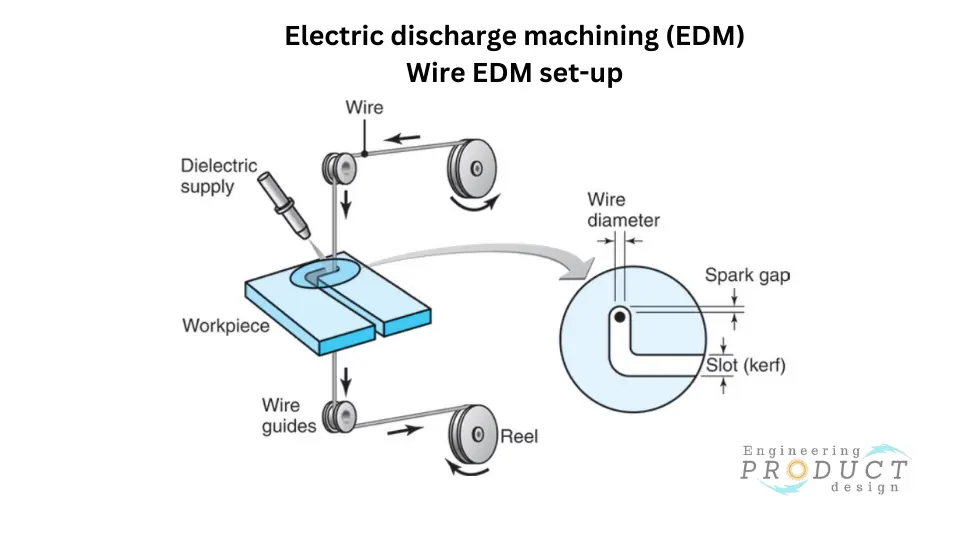
Wire EDM or electrical-discharge wire cutting is a type of EDM that involves a wire moving slowly at a constant speed along a path provided by a CNC program to achieve the desired shape. The wire removes material along the path and at a constant kerf whose size depends on the wire diameter.
The applications of wire EDM generally include the production of plates, punches, dies, tools, and components for electronics testing and assembly.
The wire used in this process is usually placed between two spools to ensure the portion actively cutting the material is continuously changed. This feature ensures that the wire does not break due to excessive erosion.
EDM wires are typically made of tungsten, copper, brass, or molybdenum. However, alternatives such as steel-cored, multi-coated, zinc-coated, and brass-coated wires are also available.
Since the kerf size depends on the wire diameter, wires come in different diameters for different applications, ranging from 0.02 mm to 0.3 mm, with 0.25mm being the most commonly used diameter.
Electrical-discharge grinding
EDG is an electrical-discharge machining (EDM) type that uses a grinding wheel as the electrode. Graphite and brass are the most common materials for the grinding wheel. Another feature of the grinding wheel is that it contains no abrasive element. As with a regular electrode, the process generates sparks between the grinding wheel and the workpiece to remove material. The main characteristic of EDG is that there is a chemical action where the sparks separate the oxide layer from the surface of the workpiece, thus cleaning the surface as it happens in regular grinding. EDG provides a high-quality surface finish to carbide tools, dies, and surgical needles, among other applications.
Hole-drilling EDM
As the name suggests, this EDM type focuses on creating holes in the workpiece.
Hole-drilling EDM involves a rotating tool electrode that can create minuscule holes ranging from 0.25mm to 6.1mm in diameter. The holes created with this process need no deburring after drilling since the dielectric fluid cleans the hole from any remaining debris. This characteristic makes this hole-drilling method excel above traditional ones.
Common applications include:
- Internal cooling for turbine blades.
- Medical equipment.
- Tools and moulds for semiconductor production.
Advantages of EDM
- Machining accuracy – EDM can achieve tight tolerances within the millionths of an inch range.
- Machining capabilities – EDM can work with a wide range of material hardness and brittleness. Therefore, manufacturers can process any conductive material, including titanium and nickel alloys.
- Complex geometry – EDM can create complex shapes with intricate features that may be difficult or impossible to achieve with conventional machining or additive manufacturing methods
- Surface finish – EDM can achieve high-quality surface finishes without post-processing. Manufacturers can benefit from obtaining end products with remarkable aesthetics and performance.
- Manufacturing efficiency – EDM is a highly efficient production process since it can reduce or eliminate the need for post-processing. Therefore, manufacturers use it to save the cost and time required by those extra processes.
- Limited distortion –EDM can limit internal stress and distortion on the surface since there is no heat accumulation, tearing, or fracture.
Disadvantages of EDM
- Material limitations – EDM can work only on conductive materials. So, manufacturers cannot use it to machine plastics and composites.
- Electrode wear – EDM tool electrodes can wear out during the process, and changing them is often required. As a result, manufacturers see their operational costs move higher.
- Machining speed –EDM cannot remove material faster than other manufacturing processes. So, manufacturers find it more costly than alternatives on a per-part basis.
- Rework requirements – The workpiece can sometimes require rework due to electrode burn-off.
What material can be EDM?
As described above, EDM can process any conductive material. It means all metals can be electrical discharge machined.
The most popular material options include:
- Hardened steels
- Stainless steels
- Titanium
- Tungsten
- Molybdenum
It is worth highlighting that soft metals can be EDM, but it is not cost-effective because it is cheaper to use traditional methods. EDM becomes an option for these materials only when the part requires single-stage machining or when the application requires avoiding extra heat on the piece. Examples of materials that fall in this group are:
- Non-hardened steels
- Copper
- Bronze
- Brass
- Aluminium alloys
Plasma Cutting
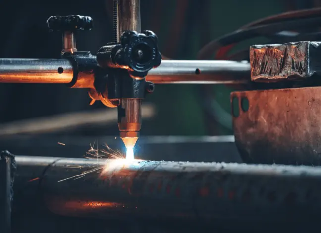
Plasma cutting is a manufacturing method to process conductive materials that is usually applied to cut parts out of metal sheets.
What is Plasma Cutting?
Plasma cutting is a manufacturing process where a high-velocity jet of ionised gas melts and cuts through electrically conductive materials. Gases commonly used in this cutting process include compressed air, oxygen, argon, hydrogen, nitrogen, and some combinations.
Plasma cutting, also known as Plasma arc cutting is widely used in several industries, such as metal manufacturing, construction, Maritime (shipbuilding), automotive and Oil and gas, to produce structural beams, Ship hulls, bulkheads, gunwales, Platforms and storage tanks, and Vehicle bodywork.
How does plasma cutting work?
When machines are automated, the CNC program must be loaded into the machine to provide the instructions that will dictate the movement of the cutter. However, there are some manual plasma cutters where the operator dictates the movement.
The critical components of a plasma arc cutting machine are:
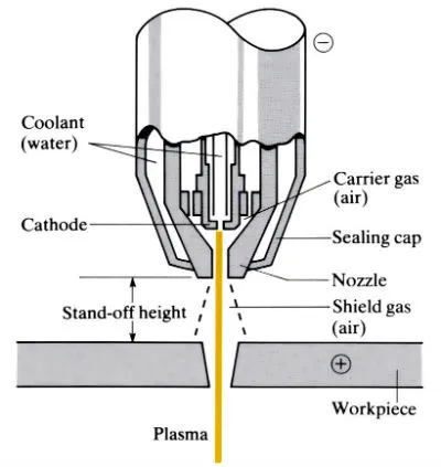
- DC power supply
- An electrode
- A swirl ring
- Cutting tip or nozzle
- Nozzle holder or shield cup
- Shield gas
- Plasma gas
In general, the process of plasma cutting involves the following steps:
- Electric arc generation – The DC power supply energises the electrode to generate an electric arc.
- Gas supply – An ignition or plasma gas supply helps complete the arc generation, also known as the pilot arc.
- Ionization – The copper nozzle and a secondary gas, the shield gas, constrict the electric arc, thus increasing the temperature and ionising the air gap between the electrode and the workpiece.
- Plasma generation and arc transfer – The constricted electric arc ionises and heats the gas to temperatures as high as 20,000 °C. This extreme temperature converts the gas into what is known as the fourth state of matter, plasma. Then, the arc transfers to the workpiece thanks to the conductivity of the plasma.
- Cutting – The plasma gas is pushed at high pressure and speed onto the workpiece, thus cutting the material by melting it. Here, the secondary gas also plays a critical role since it cools down the torch and protects the cutting area from external contamination.
What are the advantages of plasma arc cutting?
- Increased sheet thickness – Hand-operated plasma arc cutting can cut sheets with a thickness of up to 38 mm, which is more than the laser cutting capabilities. Moreover, manufacturers can use automated cutters to cut sheets up to 150 mm. However, this requires a much higher energy input.
- Lower cost – Plasma arc cutting usually requires a lower initial investment than laser cutting.
- Low maintenance – Plasma arc cutting machines require less maintenance than laser cutting, and replacement parts are cheaper.
- Speed – Plasma arc cutting can cut thick sheet metal faster than laser cutting.
- No warping – Plasma arc cutting speed prevents heat transfer and accumulation. So, no warping is generated.
What are the disadvantages of plasma arc cutting?
- Material limitation – Plasma arc cutting is limited to conductive materials. Manufacturers needing to cut other types of material may need to look for an alternative.
- Low-quality finish – Plasma arc cutting leaves a lot of molten residue and rough edges.
- Post-processing requirements – Plasma arc cutting requires post-processing due to its low-quality finish. Deburring and polishing are common after cutting process.
- Larger kerf – Cutting process cannot achieve as highly accurate and delicate contours as laser cutting.
Common plasma arc cutting materials
Plasma arc cutting works only with conductive materials since the workpiece must be able to receive the electric arc and complete the circuit. Therefore, the most common plasma-cutting materials are:
- Mild Steel
- Carbon Steel
- Stainless steels
- Aluminium alloys
- Brass
- Copper
| Material | Melting Point (°C) | Thermal Conductivity (W/m·K) | Electrical Conductivity (% IACS) |
|---|---|---|---|
| Mild Steel | 1425-1540 | 50 | 10 |
| Carbon Steel | 1425-1540 | 50 | 10 |
| Stainless Steel | 1375-1530 | 16 | 2-4 |
| Aluminium Alloys | 463-671 | 121-237 | 30-62 |
| Brass | 900-940 | 109 | 28 |
| Copper | 1085 | 401 | 100 |
Notes about the material properties
- Melting Point: Indicates the temperature at which the material will melt. Materials with lower melting points generally cut faster but require careful control to avoid melting too much.
- Thermal Conductivity: Higher thermal conductivity materials dissipate heat quickly, which can affect the quality and speed of the cut.
- Electrical Conductivity: Important for plasma cutting as it relies on the material’s ability to conduct electricity to form the plasma arc.
These properties influence how effectively each material can be cut using plasma cutting techniques.
Laser Beam Machining (LBM)
Laser cutting is a manufacturing process which uses a focused laser beam to precisely cut, machine, or engrave materials such as metal, plastic, or wood.
What is Laser Cutting?
Laser cutting or Laser Beam Machining (LBM) is a manufacturing process that involves cutting through the material by focusing a high-energy laser. In other words, laser cutting involves cutting a workpiece by melting and evaporating the corresponding portions of material with a focused light beam that moves along a path provided by a CNC code.
LASER is an acronym for Light Amplification by Stimulated Emission of Radiation.
Industries such as Automotive, Aerospace, Medical equipment manufacturing, Electronics and Consumer goods use Laser cutting extensively to make components like gearwheels, exhaust system protection, cooling holes in turbine blades and jet engine vanes, knives and blades for household appliances and Medical implants, pacemakers, stents, and other medical equipment.
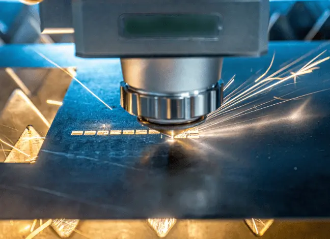
How does laser cutting work?
The main components of a laser cutter include:
| Laser resonator – Laser Generator | Laser resonator – Laser Generator |
| Beam bender or mirror | Beam bender or mirror |
| Laser-focusing head | Laser-focusing head |
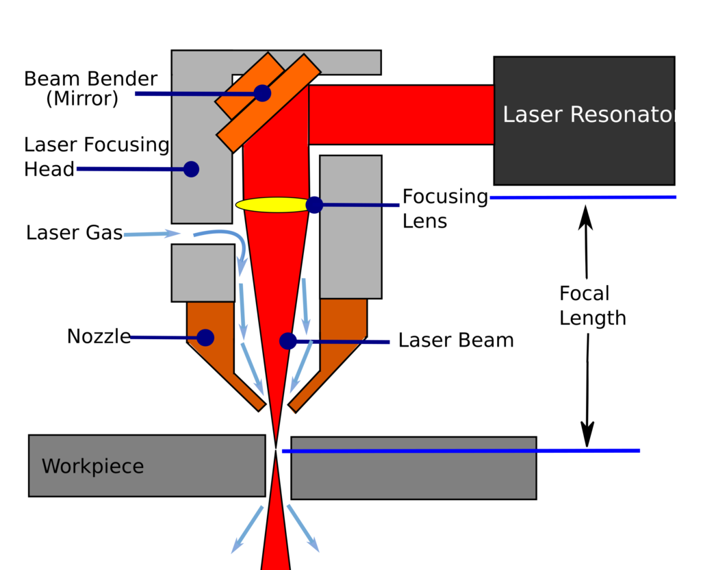
The process takes a series of steps that start with generating and programming the desired cutting pattern. From here, the machine is loaded with the program to begin cutting.
- Laser generation – The resonator receives energy from the power supply and generates the laser beam.
- Laser amplification – The two mirrors located at the ends of the head amplify the intensity of the laser beam by making it flow through the amplifying medium.
- Laser direction and focus – Depending on the type of laser cutting technology, a fibre optic cable or a group of mirrors in the focusing head give direction to the laser beam. Then, a lens achieves the energy focus required for the laser beam to be able to cut.
- Gas supply – The cutter blows gas through the nozzle to clear the molten from the kerf.
- Cutting – Once the head focuses the energy, the laser melts and evaporates the material. The movement of the cutting head occurs automatically along the pattern created in the CNC program, thus making the corresponding kerf. In some cases, the workpiece moves while the cutting head stays still.
Types of Laser beam machining
There are different laser cutting technologies; the main difference is the medium they use to remove the molten from the workpiece. However, there may be other relevant differences.
- Fusion Laser Beam Machining
- Flame Laser Beam Machining
- Remote Laser Beam Machining
- Thermal stress fracture
- Stealth dicing
- Vector Laser Beam Machining
Laser types in Laser beam machining
- CO2 Lasers – Manufacturers use Carbon Dioxide (CO2) lasers for cutting non-metallic materials like wood, acrylic, plastic, fabric, leather, and paper. If coated with a layer, the CO2 laser can cut metal to stop the reflection.
- Nd: YAG Lasers – These lasers can cut many materials, including metals and non-metals, but they are less common than CO2 and fibre lasers.
- Fibre Laser Cutting – Fibre lasers are ideal for cutting metals, ferrous metals like steel and non-ferrous metals like aluminium, copper, and brass. They are highly efficient and have a high cutting speed.
- Direct Diode Laser Cutting – These types of lasers are known for their high energy efficiency and use diode lasers, which are becoming more popular for cutting thin sheet metals.
- Solid State Laser Cutting – Solid State Laser includes various lasers that use a solid medium, such as Yttrium Aluminium Garnet (YAG) or Ruby, to generate the laser beam. Manufacturers use Solid-state lasers to cut metals, ceramics, and some plastics.
Common Laser cutting materials
Laser-cutting materials
- Mild steels
- Stainless steels
- Aluminium alloys
- Copper
- Brass
- Foiled sheets
- Galvanized sheets
- Carbon
- Glass
- Wood
- Leather
What are the advantages of Laser cutting?
- Materials variety – Laser cutting can process various metallic and non-metallic materials. Therefore, manufacturers can use it for many applications and industries.
- High precision and accuracy – Laser cutting can achieve thin cuts with kerfs below 0.5mm. Moreover, manufacturers applying laser cutting can achieve tolerances of +/-0.1mm.
- High-quality finish – Laser cutting can achieve edges with low roughness and almost no burr formation. Manufacturers can benefit from lower costs and increased productivity as it reduces the need for post-processing.
- High speed and set-up efficiency – Laser cutting can cut at very high speeds depending on the power supply and the thickness of the workpiece. For example, a 2mm steel plate can be cut 30mm/s using a CO2 laser cutter at 200W. Also, laser cutting only requires setting up the cutting program since there is neither tool changing nor clamps or other workpiece holders to be set. It only requires placing the material on the cutting area.
- Non-contact – It uses energy to cut through the workpiece. Therefore, no contact between the cutting tool and the material eliminates the tool wear problem.
What are the disadvantages of laser cutting?
- Sheet Thickness – Laser cutting can work only with 0.5-30mm material sheets. This range is low compared to alternatives such as plasma cutting.
- Power efficiency – It is a high power consuming manufacturing process. As a result, manufacturers see an increase in operational costs.
- Initial investment – The cutting process requires a high initial investment. Manufacturers may find cheaper alternatives for their applications.
- Material limitation – Laser beam machining cannot cut highly reflective material directly since the surface of the workpiece could reflect the laser beam into the machine, which could result in significant damage. However, this potential damage can be diminished by preparing the surface with a covering layer that absorbs the light from the laser. Also, modern laser cutters already integrate a self-protection system. An alternative would be using other machining technologies.
- Heat generation – might affect the material warping and deformation – thermally sensitive material.
What is the difference between laser and plasma cutting?
| Feature | Laser cutting | Plasma cutting |
| Heat source | Concentrated beam of light | Jet of plasma |
| Materials cut | Metals, plastics, wood, glass | Metals, plastics, ceramics |
| Cut thickness | Thin to thick | Thick to thin |
| Cut accuracy | Very high | High |
| Cut quality | Excellent | Good |
| Speed | Fast | Fast to medium |
| Cost | High | Low to medium |
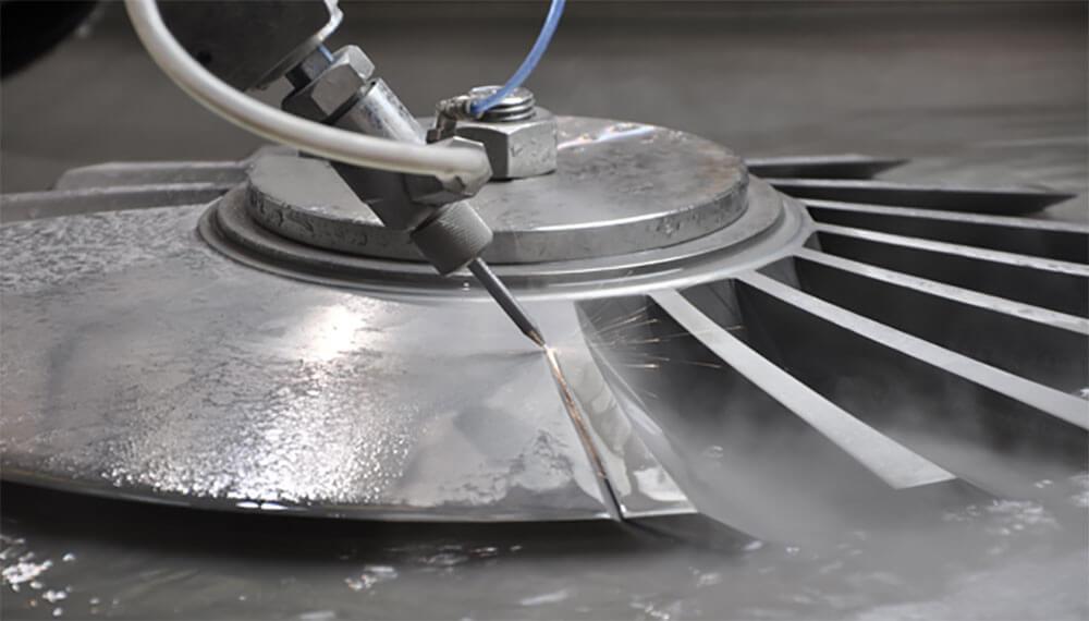
Water Jet Machining (WJM)
Water jet machining is a CNC cutting process in which a water jet at very high pressure is used to cut material to make 3D parts.
What is Water Jet Machining?
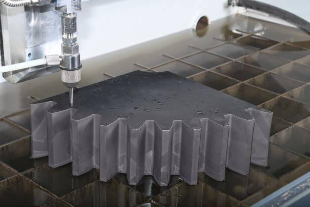
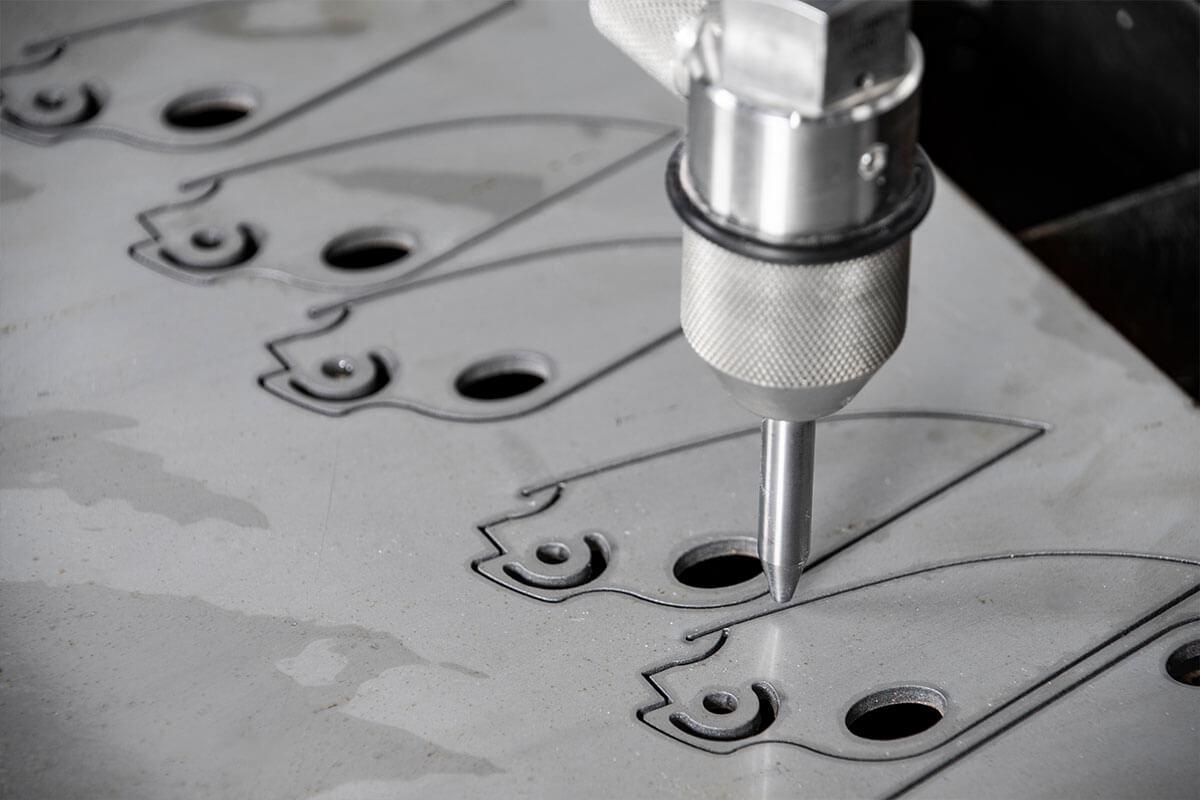
Water Jet Machining (WJM), also known as Hydrodynamic machining or Water Jet Cutting (WJC), is a CNC cutting process that uses a high-pressure water jet to cut material and create 3D parts. The high-pressure water jet is strong enough to cut metal, plastic, textile, composites, fabrics, wood, cardboard, paper, tiles, stones, carpets, leather and rubber by cutting a narrow groove in the material. ( Shown in the image below).
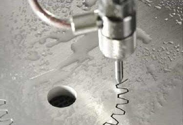
WJM is a widely used manufacturing process in Automotive, Aerospace, Food processing, Defence and military, Medical, surgical equipment, Architectural, and mining because it can cut material or shape that is difficult to cut using traditional manufacturing methods.
Although water jet cutting is typically associated with 2D machining, manufacturers use Multi-axis CNC machines and articulated robotic arms with cutting nozzles to cut and create 3D shapes. The food processing industry also uses it to cut and slice food products because it is a more efficient and clean operation than other cutting processes.
Types of Water Jet Machining
Pure water jet machining and Abrasive Water jet machining are the two basic types of WJM processes.
Pure Water Jet Machining
As the name suggests, the Pure WJM uses pure water without add-ons as the high-pressure cutting medium to cut through the material.
Abrasive Water-jet Machining
Abrasive water jet machining (AWJM) uses abrasive particles in the water jet, such as garnet abrasives, silicon carbide or aluminium oxide, to increase the material-removal rate significantly. As a result, metallic, non-metallic, plastic and advanced composite materials of various thicknesses can be cut in single or multilayers without compromising accuracy. AWJM machine controls the level of abrasives and uses nozzles made of rubies, sapphires, and diamonds to achieve the optimum cut.
Key characteristics WJM
- WJM is ideal for heat-sensitive materials that cannot be machined using heat-producing processes
- The process may not be cost-effective for applications requiring high production rates due to low cutting speed for metal or thick material
- Complex three-dimensional parts can be machined economically to finish dimensions using multiple-axis and robot-controlled machines.
- Pressures of around 350 – 400 MPa (50000 – 60000 psi) are typically used for efficient operation, though WJM machines can generate pressures of up to 1400 MPa (20000 psi).
Water Jet Cutting Applications
WJM is ideal for heat-sensitive materials that cannot be machined using heat-producing processes.
- Aerospace
- Electronics
- Architectural / Design /Artwork
- Automotive
- Food
Materials
Glass
WJM technology is widely used to cut glass. The process can cut glass up to 180 mm (7″) to create parts such as glass mirrors, glass partitioning, glass splashback, and architectural applications. Even 3D intricate cut designs can be placed on a glass workpiece using the 5-axis waterjet cutters.
Metal
Water jet cutting can cut any metal, including common CNC machining aluminium alloys, hardened tool steel, titanium, copper, brass, and other exotic metals. Water jet cutting preserves the workpiece’s structural and chemical integrity because it doesn’t raise the temperature.
Water jet cutting’s maximum cutting thickness varies depending on the metal. Aluminium – 450 mm (18″), Steel – 300 mm (12″) and Brass and Copper – 250 mm (10″).
Plastics
Traditional machining of plastics produces toxic fumes due to cutting tools getting hot. As a result, water jet cutting is one of the safest options for cutting plastics because no temperature rise occurs. In addition, the process can cut up to 100 mm (4″) thick toughest acrylics.
Composites
Composites like fibreglass and carbon fibre can crack or strain during traditional machining. Because the force is limited at the impact point, waterjet cutting is one of the best cutting technologies for composites. Maximum cutting thickness – 150 mm (6″)
Ceramics
Because of their toughness, ceramics are difficult to machine and frequently require costly saw blades. Hence water jet cutting is a less expensive technique for ceramic machining, and it can cut ceramics up to 200 mm (8″) thick.
Foam and Rubber
Rubber, like plastic, emits toxic fumes at high temperatures. Therefore, manufacturers use waterjet cutting worldwide to process rubber because of its safety benefits. The maximum cutting thickness supported by this method is 250 mm (10″) for rubber and 750 mm (30″) for foam.
Others
Stones, Tiles, Textiles, Paper, Cardboard, Food, Plasterboards,
Electrochemical Machining (ECM)
Electrochemical Machining (ECM) is an advanced machining process that uses electrical energy to remove material from a workpiece through electrochemical reactions. Unlike traditional mechanical cutting methods, ECM is a non-contact process where material removal occurs without generating heat or mechanical stresses.
Types of Electrochemical Machining
- Conventional ECM
- Pulsed ECM
- Jet ECM
- Flow-Assisted ECM
- Electrochemical Grinding (ECG)
Thermal Energy Processes
Thermal Energy Processes (TEPs) encompass a range of advanced machining techniques that use concentrated thermal energy to cut, shape, or modify materials. Unlike traditional machining, which relies on mechanical force and cutting tools, TEPs harness heat to melt, vaporize, or chemically alter material at precise locations. These processes are highly effective for working with tough, hard-to-machine materials and achieving complex geometries.
Types of Thermal Energy Processes
- Electron Beam Machining (EBM): Uses a focused beam of high-energy electrons to melt and vaporize material, capable of ultra-fine cutting and welding.
- Laser Beam Machining (LBM): Employs a concentrated laser beam to precisely cut or engrave materials, known for its versatility and high precision.
- Plasma Arc Machining (PAM): Involves a high-velocity stream of ionized gas (plasma) to melt and blow away material, effective for cutting thick and conductive materials.
- Ion Beam Machining (IBM): Uses accelerated ions to etch or mill surfaces at a microscopic level, suitable for very fine features and surface modifications.
Chemical Machining
Chemical Machining (CM) is a precise and versatile manufacturing process used to selectively remove material from a workpiece through chemical dissolution. Unlike traditional mechanical cutting methods, CM involves no physical contact between a cutting tool and the workpiece, making it ideal for producing intricate shapes and fine details with high precision.
Types of Chemical Machining
- Chemical Milling: Involves immersing the workpiece in a chemical bath that selectively dissolves material from exposed surfaces, leaving behind the desired shape or profile.
- Photochemical Machining (Photochemical Etching): Utilizes a light-sensitive mask (photoresist) to protect certain areas of the workpiece from chemical etching, allowing for the precise creation of complex patterns and designs.
Recommended reference
- Kalpakjian, S., & Schmid, S. R. (2015). Manufacturing Engineering and Technology in SI Units, Global Edition. 8th ed. Pearson Education.
- Friedhoff, S., & Sweeney, T. (2008). Plasma Cutting Handbook: Choosing Plasma Cutting Systems and Plasma Torches. Industrial Press.
- Golobic, I. (2012). Plasma Cutting Handbook: Techniques, Applications, and Systems. McGraw-Hill Education.
- McManus, H. (2016). Plasma Cutting Technology: Theory and Practice. Springer.
- Ashby, M.F., 2005. Material Selection in Mechanical Design. 3rd ed. Oxford: Butterworth-Heinemann.
- Beeley, P. (2001). Foundry Technology (Second edition ed.). Oxford: Butterworth Heinemann.
- Groover, Mikell P.(2010). Fundamentals of Modern Manufacturing: Materials, Processes, and Systems (Forth edition ed.). Hoboken, NJ: J. Wiley & Sons, 2010.