Plastic Injection moulding is a widely used manufacturing process to produce plastic components due to its affordability, effectiveness, and high reliability.
What is Injection moulding?
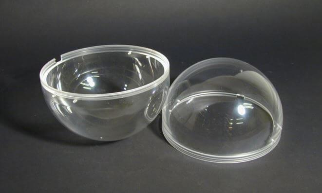
Injection Moulding (IM) is a manufacturing process in which a polymer is heated to a highly molten state and forced to flow under high pressure into a mould. The molten plastic then cools and solidifies inside the desired part-shaped cavity. Finally, the moulded part, known typically as moulding, is extracted from the mould.
Plastics and elastomers are the most common moulded material, and manufacturers produce large quantities of mouldings. Similar to metal casting and 3D Printing, IM can produce distinctive near-net shape parts with complex and intricate shapes.
Although larger parts could take 60 seconds or longer, the typical production cycle time is between 10 and 30 seconds. Also, the mould can contain more than one cavity, so multiple mouldings are produced each cycle.
Because it produces plastic mouldings in large quantities at a meagre cost per unit, injection moulding is extremely common. Two advantages of injection moulding are its high repeatability and substantial design flexibility. However, economic factors are typically the primary constraint on injection moulding because of the high initial mould investment needed. The turnaround time for initial production is also very long.
How does Injection moulding work?
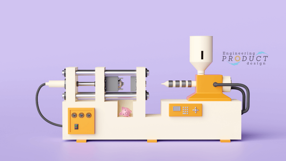
The core requirement of an Injection moulding machine is to melt the plastic granules, push them into the mould cavity and, once cooled, open the mould cavity to release the parts. Hence, an Injection moulding machine consists of a plastic Injection unit, a mould clamping unit and a Mould.
Plastic moulding machines are adapted and evolved from metal die-casting machines pioneered by John Hyatt, who patented a plastic Injection moulding machine in 1872.
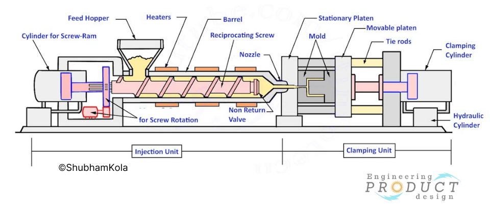
The image above shows a typical injection moulding machine, which shows all the essential components viz Injection unit, Clamping unit and the mould.
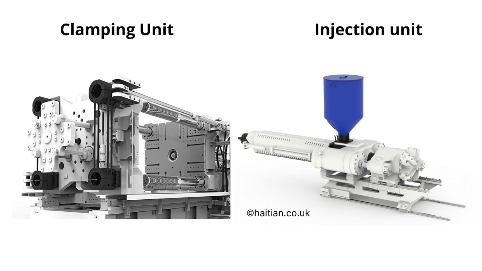
Injection unit – The Injection unit consists of a material feeding hopper, a barrel with an extruding screw and a hydraulic ram to push the injection unit towards the mould cavity entrance. The Screw mixes the materials and then heats and forces the molten plastic inside the mould. The Screw and barrel geometry has been optimised to help increase the pressure to suitable levels and melt the material.
Clamping unit – The injection moulding machine clamping unit holds the two halves of the mould clamped together during the injection cycle to resist the injection force. It also helps the mould open and closes correctly in sync with the injection cycle keeping the alignment of the two halves.
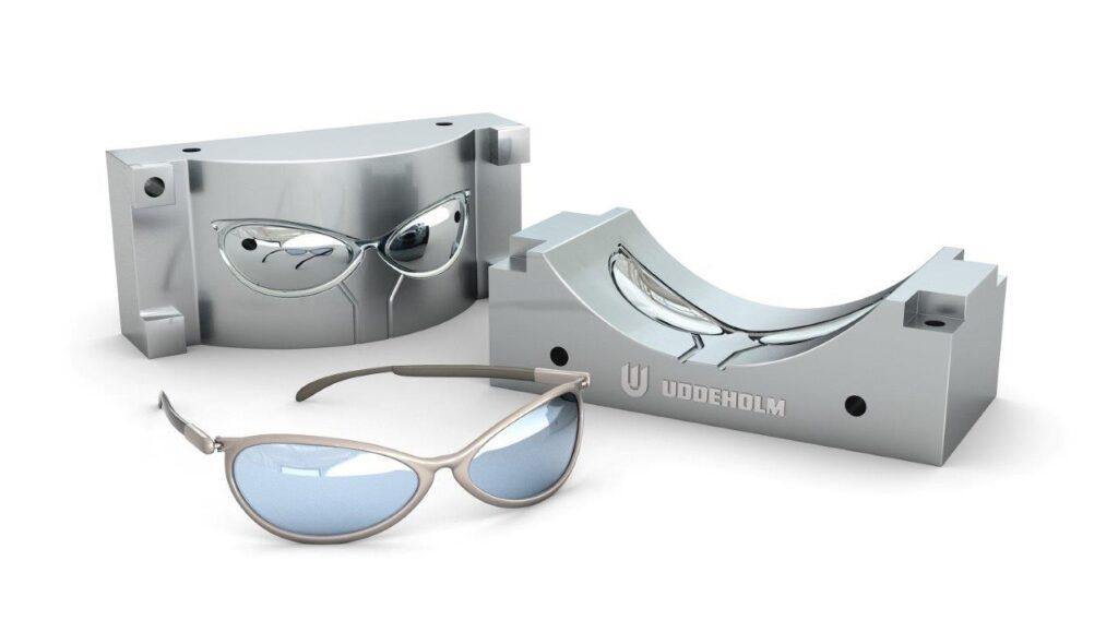
Mould – A mould is a split metal block with a cavity in the shape of the desired part. The manufacturers typically use tool steel, Aluminium and beryllium copper for moulds. Moulds could have either a single cavity or multiple of the same part or multiple parts, which allows the manufacturer to mould multiple parts together in one injection cycle.
The first step in the injection moulding process is mould making. Once the mould is designed and built, then the trials begin. First, the manufacturer runs through trials to get the process parameters set. Typically, the first samples are called T1 samples for customer approval.
So, how does the Injection moulding process work?
- The manufacturer fills the feed hopper with dried polymer granules, colouring pigments, and other polymer fillers and additives.
- The machine then feeds the material mix into the barrel, where the reciprocating Screw simultaneously heats, mixes, and moves the material in the direction of the mould.
- When the material reaches the correct temperature inside the barrel, the injection moulding machine is ready for its Injection moulding cycle.
A typical Injection moulding cycle starts.
- Once the injection moulding cycle starts, the machine closes the mould, and the clamping unit clamps the mould halves together.
- When the material reaches the correct temperature and the mould is ready, the hydraulic cylinder (Ram) moves forward, injecting the molten plastic into the mould cavity through mould runners. This is called a Shot.
- The molten plastic cools when it touches the colder mould surface. Ram maintains the pressure to inject more molten plastic into the cavity to compensate for material contraction during cooling.
- After the material solidifies inside the mould cavity, the injection unit retracts from the clamping unit, and the clamping unit opens the mould.
- When the mould tool opens, built-in ejector pins eject the moulded part.
The finished component goes through a few post-processing steps. These procedures include removing surplus material and structural supports, finishing the surface, and, if necessary, heat treating, painting, and electroplating.
Application of Injection moulding (Characteristics)
Injection moulding is one of the highly effective manufacturing processes for producing plastic parts. Hence it is used in various consumer, industrial, automotive, manufacturing and food processing industries.
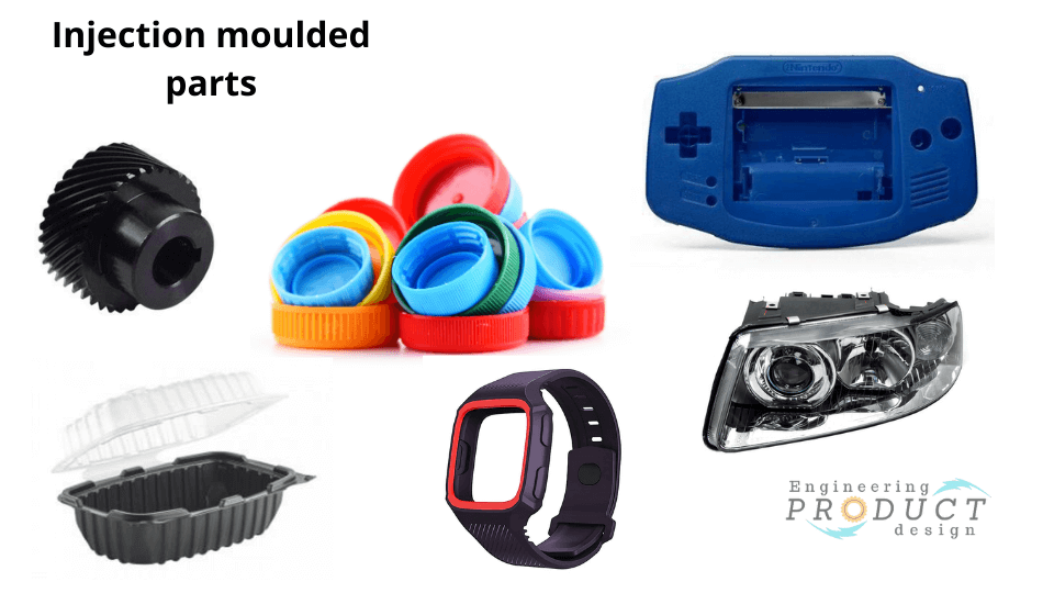
- Polymer optics used products like bar-code scanners
- Automotive components such as car bumpers
- Consumer electronics such as sensor housing, smartwatch housing and thermal cameras. Typically most of them use PS and ABS for their good electrical insulation properties and excellent impact resistance.
- Food processing and packaging components
- Kitchen Appliances
- Garden furniture
Advantages and Disadvantages of Injection moulding
Advantages of Injection moulding
- Injection moulding can make complex and intricate shapes with very tight tolerances.
- IM parts can range from 50g up to about 25 kg.
- Easy to scale up production, production cost drops with increasing part count and produces repeated parts.
- Labour cost is low because IM is a semi-automated manufacturing process with a single operator managing the machine.
- Wide range of material choices, although most common Injection moulding materials make up 90% of the injection mouldings
- IM can manufacture near-net shape parts with little scrap reducing waste compared to other manufacturing processes like CNC machining.
- Design freedom with features, material and colour choices. Material can also be modified to suit the application and operation environment by adding add-ons such as UV additives, fibres, and glass beads.
- IM is the most widely used moulding process for thermoplastics.
- IM manufacturing is very efficient and fast compared to CNC machining and 3D Printing.
Disadvantages of Injection moulding
While injection moulding has some benefits, there are also some drawbacks.
- The initial cost is too high due to mould tool cost. Hence Injection moulding is economical only for large quantities of parts.
- IM needs a few prototypes and iterations to correct the part, adding time and cost; hence the initial lead times are long.
- Not suitable for a large part as the mould tool and machine limit the size. This can be overcome by making multiple parts to create a large assembly. Multiple parts can be cut into the same mould with multiple cavities.
- Part design restrictions such as undercuts add cost
- Design changes and interactions are very costly and time-consuming. Hence use processes like 3D Printing and Vacuum casting to prototype the part before going into injection moulding.
- Thermosets and elastomers can only be Injection moulded with modification to the process and equipment.
- The manufacturer needs to clean the spruce and the runners from the part ejected from the mould tool. Sometimes clever three-plate tools can remove spruce and runners, but they are very costly.
Plastic moulding material
Injection moulding is the most widely used moulding process for thermoplastics. In 2021, it was estimated that the world produced 390.7 million metric tonnes of plastic parts.
Since thermoplastics and thermosets are different in how they react to temperature, some thermosets, like silicone and elastomers, are moulded with equipment and operating parameters modifications to allow for cross-linking of these materials. A prime example of a modified Injection moulding manufacturing process is Liquid Silicone rubber moulding process.
List of the most widely used thermoplastics in injection moulding are:
- Acrylonitrile Butadiene Styrene (ABS) – 27% of the world’s output
- Polycarbonate (PC)
- Polycarbonate + Acrylonitrile Butadiene Styrene (PC/ABS)
- High Impact Polystyrene (HIPS) – 8% of global production
- Polyphthalamide (PPA)
- Polymethyl Methacrylate Acrylic (PMMA)
- High-Density Polyethylene (HDPE) (15% of the world’s production in PE)
- Low-Density Polyethylene (LDPE) (15% of the world’s production in PE)
- Polypropylene (PP) – 38% of the world’s production
- Polyoxymethylene (POM)
Read the ten most common Injection moulding materials to understand their application and properties.
Common Injection Moulding defects
Learning about how to design for Injection moulding and getting moulding companies involved early on your design journey is vital to a successful moulding by avoiding common Injection moulding defects.
- Shrinkage – The common issue of Injection moulding is shrinkage. Since Polymers have a high thermal expansion coefficient compared to metal, shrinkage can occur during the cooling cycle of the moulding process.
- Short shots – A short shot is when the injected molten plastic solidifies inside the mould before filling the mould cavity. These are due to a lack of pressure, low temperature and low shot capacity.
- Flashing – Flashes are when the molten plastic squeezes through the gap between the two mould halves. It typically occurs near the ejection pins.
- Sink marks – Sink marks occur when the inner surface contracts and pulls the solidified outer surface inwards, creating a depression on the surface.
- Voids – Void is very similar to sink marks, but instead of pulling the outer surface, the inner surface pulls away from the solidified outer surface, creating an internal void.
- Weld lines – When the plastic flows around specific features and meets from the opposite direction, it forms a visible line called a weld line. These knit lines can affect a product’s functionality and aesthetics.
- Burn marks & Discolouration – Burn marks are stains on the Injection moulded part surfaces, typically rust-coloured.
- Flow marks – Flow lines are streaks, patterns, or lines on the moulded part due to the molten plastic’s physical path and cooling profile as it flows into the injection mould cavity.
- Delamination – Thin surface layers develop on the component due to a contaminant material, a condition known as surface delamination. These layers, which resemble coatings, can frequently be peeled off.
- Warping – Warping occurs when shrinkage occurs unevenly.
Read our 12 Injection mould defects to under stand the defects and how to avoid them.
Injection moulding vs 3d Printing
Plastic Injection moulding and 3D Printing are both manufacturing processes for making plastic parts, but they differ in how they are produced. Hence the properties of the end product would have different mechanical properties and surface finish.
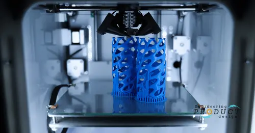
3D Printing, known as additive manufacturing, creates 3D objects by adding layer upon layer of material. As described in the previous section, injection moulding makes parts by injecting molten plastic into a mould cavity. Let’s look at the difference between the two.
- Compared to 3d Printing, the initial cost is the IM process’s biggest drawback.
- 3D Printing is a great choice to prototype an Injection moulding part to fine-tune with quick iterations.
- Although the 3D printing product cycle time is slow, the initial setup time is quick as most 3d printing technologies can print directly from the 3D CAD model.
- Injection moulding is cost-effective for larger volumes
- 3D Printing is quicker to set up, allows for frequent design changes, and is better for intricate designs.
- Use 3D Printing for small batches of prototypes and pre-production test units. A great choice for early product design stages where quick design changes have to be tested.
Injection moulding vs Vacuum forming (Thermoforming)
Vacuum forming is a manufacturing process in which a sheet of plastic material is heated to a malleable forming temperature, formed to a specific shape in a mould, and trimmed to create a finished product. The process uses vacuum pressure to draw the heated plastic sheet into the mould, which creates a hollow part with the desired shape. This technique is commonly used for creating complex, lightweight, and cost-effective plastic products such as blister packaging, automotive parts, and toy models.