A Key is used on a shaft keyway to retain mechanical power transmission components such as gear drives and pulleys to transmit power.
What is a key & keyway?
A key and the keyway make up a Keyed joint to secure the hub and the shaft to prevent relative movement between a power transmitting shaft and an attached component. For example, Gear drives, Pulleys or Sprockets are connected securely using keys to the power transmitting shaft.
Keyed joints are an important part of mechanical power transmission elements shaft and couplings, where it ensures the connection transmits the load, power & rotation without slipping and within the accuracy requirement of the design.
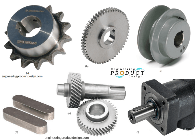
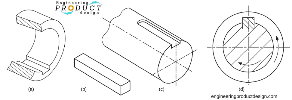
A key is usually made from steel and is inserted or mounted between the shaft and the hub of the component in an axial direction to prevent relative movement. Keyseat is a recess in the shaft, and the Keyway is the recess in the hub to receive the key and thus securely lock the component. Generally, the term keyseat is rarely used as keyway is referred to both recesses in the industry.
Shaft and hub keyways are often cut on key seating machines but can also be made using broaching, milling, shaping, and slotting EDM.
Retention elements such as Splines, flexible couplings, and tapered joints are also used. Set screws and pins can also be used if it’s a very low-power transmission. If the set screws or, in some cases keyed joints are to be used, there must be a method of axial constraints such as circlips and retaining rings.
Advantages & limits of keyed joints
There are various advantages, and disadvantages of using shaft keys hence proper consideration must be given to the finer details of the overall design to evaluate the suitability of the keyed joint.
Advantages of shaft keys & keyed joint
- Cheap manufacturing cost
- Well-standardised ( ISO, BS, DIN and ANSI)
- Medium to High torque transmission
- Easy mount and dismount, hence easily reusable
Disadvantages of shaft keys & keyed joint
- Not suitable for alternating directional loads and shocks
- Possible axial displacement of hub unless locked by an extra component such as a set screw or retainer rings
- Over time keyed joints might become very difficult to dismantle
- Keyways introduce stress points due to the notch effect and reduce shaft strength
- Introduces shaft imbalance
- Difficult to calculate and combine the load-carrying and the tolerance stack analysis hence keyed joints are over-dimensioned
- To transmit axial force, it needs a stop lock
Types of Keys
Shaft keys come in a wide variety of types and shapes and can be divided into four categories and subcategories.
- Sunk Keys
- Rectangular & square keys
- Parallel keys
- Gib head keys
- Feather key (sliding clearance with keys)
- Woodruff key
- Saddle keys
- Flat & Hollow saddle keys
- Tangent keys
- Round/Circular keys
Of the above types of keys, the Parallel square key and woodruff key are probably used more widely than others due to ease of use and cost.
Double key – Because of manufacturing tolerances and to avoid double fits, only one parallel key is used, but Double keys are occasionally used for very high infrequent loads. This should only be considered if the material is ductile. The calculations should be based on one and a half-parallel key.
Here’s a tabulated comparison of Sunk Keys, Saddle Keys, Tangent Keys, and Round/Circular Keys:
| Aspect | Sunk Keys | Saddle Keys | Tangent Keys | Round/Circular Keys |
| Design | Rectangular or square in cross-section. | Similar to Sunk Keys but fit into keyways in the hub. | Keys are placed tangent to the shaft and hub. | Circular or semi-circular cross-section. |
| Keyway Location | Machined into both shaft and hub. | Keyway in the hub but not in the shaft; shaft is plain. | Keyways are cut into both the shaft and the hub. | Keyways are often rounded to match the key shape. |
| Load Transmission | Transmits torque by engaging both shaft and hub. | Torque is transmitted primarily through friction and key-to-hub engagement. | Transmits torque via compression and shear forces. | Transmits torque through surface contact and shear. |
| Applications | General use, suitable for high torque applications. | Lower torque applications and are often used for smaller shafts. | Heavy-duty applications where high torque and shock loads are involved. | Used in specific applications where round keys are preferred for ease of assembly. |
| Strength | High, as they engage both the shaft and the hub. | Lower compared to Sunk Keys, it relies on friction and fitting precision. | High, suited for high torque and heavy-duty applications. | Moderate to high, depending on the fit and application. |
| Ease of Installation | Moderate; requires precise keyway cutting in both components. | It is easier than Sunk Keys; only hub needs a keyway. | Complex; requires precise alignment and cutting. | Moderate; easier to install due to the round shape. |
| Types | Rectangular, Square, Gib-head, etc. | Flat Saddle Key, Hollow Saddle Key. | Single Tangent, Double Tangent. | Full Round, Half-Round. |
| Alignment | Ensures positive alignment and reduces play. | Can tolerate some misalignment, relies on fit. | Requires precise alignment for effective torque transmission. | Tolerant of slight misalignment. |
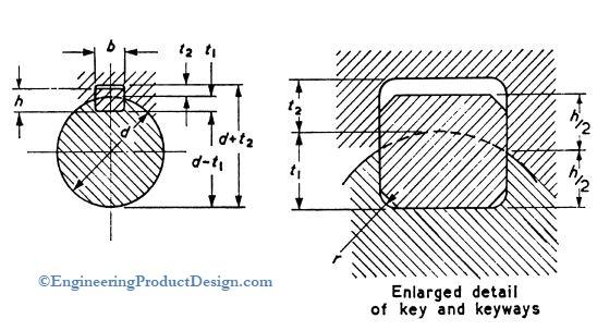
Sunk Keys
Sunk keys are sunk into the shaft for half its thickness, where the measurement is taken at the side of the key. Not along the centre line through the shaft.
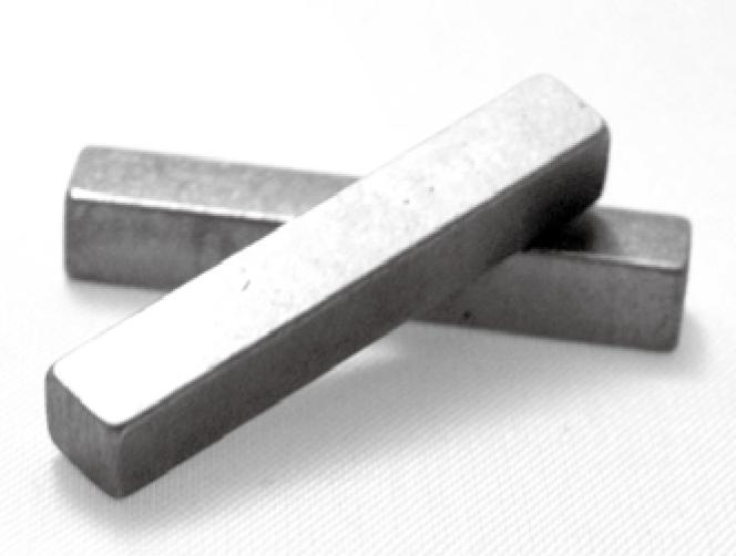
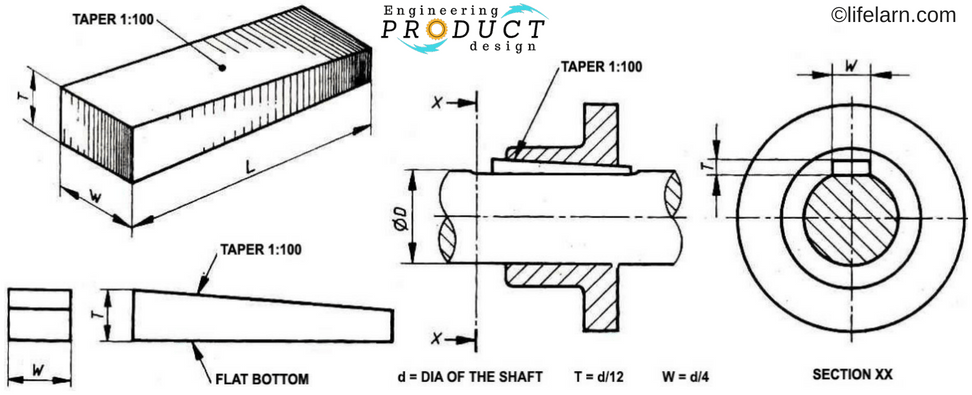
Rectangular/square keys
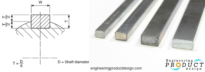
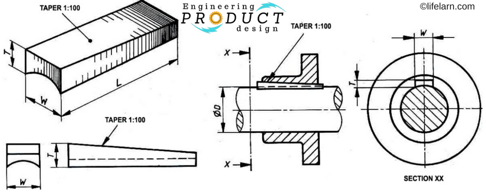
Rectangular keys, as shown, are wider than their height and are sometimes called flat keys. These are used on shafts up to about 500 mm or 20″ in diameter. The extra key width allows it to transmit greater torque without increasing the depth. An increase in depth means a weaker shaft due to a reduction in effective shaft cross-sectional area.
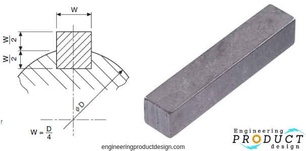
As their names suggest, square, cross-sectional keys are generally specified for shafts up to about 25mm or 1″. They can be used for larger shafts when deeper key depth is desirable than rectangular keys. An increase in depth means a weaker shaft due to reduced effective shaft cross-sectional area.
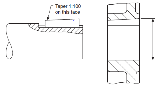
Square and rectangular keys may have a taper of 1 in 100 along the length of the key, as shown above.
Parallel sunk keys
Parallel sunk keys can be either rectangular or square sections but without the taper. These keys are inexpensive and readily available. It is one of the easiest to install. But the keys must ideally be held by a set screw through the hub. Because vibration or rotational direction reversal often pushes the key out.
These keys are generally fitted tightly to the bottom of the shaft keyway and the sides of the keyed joint, leaving a clearance at the top of the hub keyway.
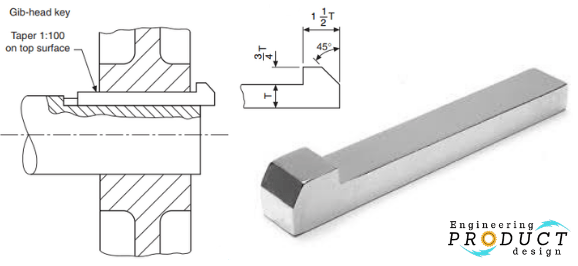
Gib head sunk keys
A Gib head-on sunk key is added to make it easier to remove. As shown in image below, Gib head sunk keys are generally rectangular or square keys with a taper on the top surface to ensure a tight fit.
Feather keys
Feather keys are attached to the shaft or the hub to permit relative axial movement. As shown in the picture, there are three main feather keys. Double-headed, Peg feather and Feather key. This enables power transmission between the shaft and hub with their parallel opposite faces while simultaneously allowing it to slide.
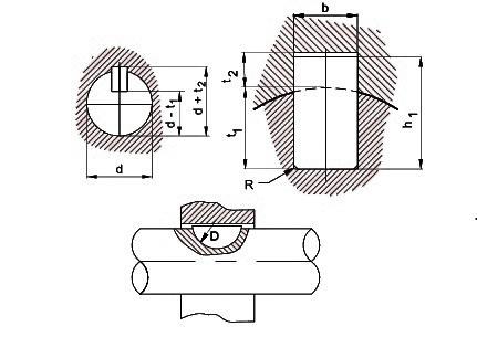
Woodruff keys
The Woodruff key is a semi-circular disc and fits into a circular recess in the shaft machined by a woodruff keyway cutter. These woodruff keys are mostly used in machine tools and automobile shafts from ¼” to 2½” (6 mm to 60 mm) in diameter. Woodruff keys cannot carry the same load as long parallel keys.
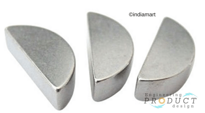
The advantage of the Woodruff key is that it can accommodate any taper in the hub keyway, and its captive and depth prevent the key from turning over.
The disadvantages or drawbacks of woodruff keys are that the depth of the keyway weakens the shaft, these cannot be used as a feather key, are difficult to install, are short, and can’t carry too much load.
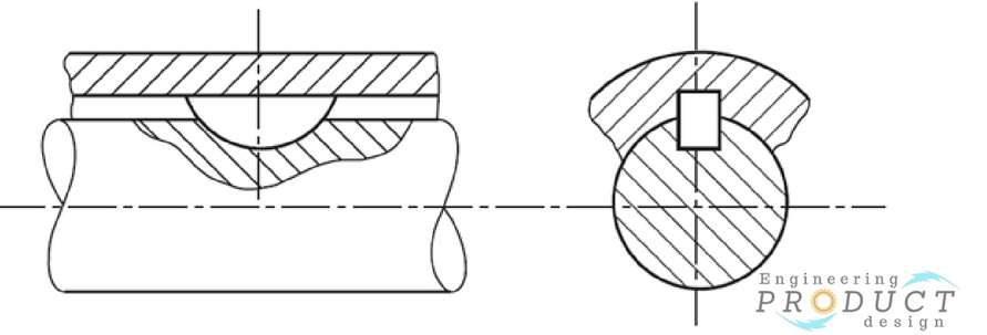
Saddle keys
Compared to sunk keys, saddle keys are not sunk into the shaft and hub instead, they are only sunk into the hub. They either sit on a flat or the circumference of the shaft. Power transmission is achieved through friction between the shaft and the key. As shown in the below figure, Saddle keys can be subdivided into Flat saddle, and Hollow saddle keys and are only suitable for light loads to avoid slipping along the shaft.
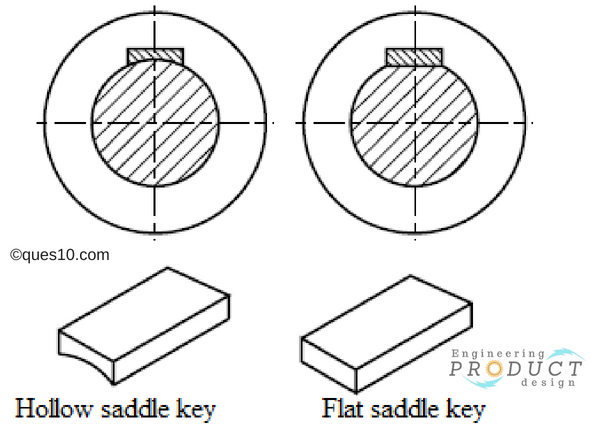
A flat saddle key is tapered at the top and flat at the bottom, as shown in the figure below. The key fits into a tapered hub keyway pushing down on the flat face of the shaft
A hollow saddle key is tapered at the top and curved at the bottom, as shown in the figure below. The key fits into a tapered hub keyway and is pushed down on the curved circumferential surface of the shaft.
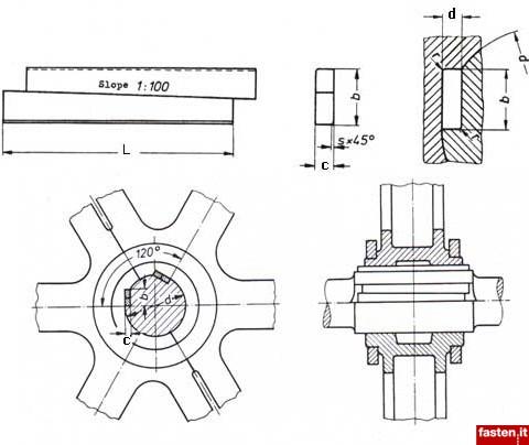
Tangent keys
The tangent keys, sometimes called Tangential keys, are fitted as a pair at right angles, as shown in the figure below, where each key only withstands torsion in one direction. These are used in large heavy-duty shafts.
Round / Circular Keys
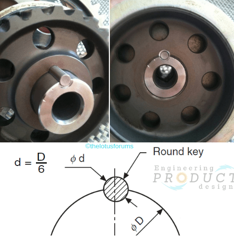
The round keys are circular in section and fit into holes drilled partly into the shaft and the hub. They have the advantage of easy manufacturing as their keyways may be drilled and reamed after the mating parts have been assembled. Round keys are usually considered to be most appropriate for low-power drives.
Shaft Key Materials
| Material | Composition | Properties | Common Applications |
| Carbon Steel | Iron, carbon (0.05-0.25%) | Moderate strength and hardness. Good machinability and ductility. | General-purpose keys in machinery automotive applications. |
| High Carbon Steel | Iron, carbon (0.6-1.0%) | High hardness and strength. Good wear resistance Less ductile and more brittle than low-carbon steel. | High-stress applications, automotive components, and tools. |
| Alloy Steel | Iron, carbon, and alloying elements (e.g., chromium, nickel, molybdenum) | High strength and toughness. Enhanced wear and fatigue resistance Good heat resistance. | High-performance applications, gears, shafts, and heavy machinery. |
| Hardened Steel | Iron, carbon, and alloying elements; heat-treated | Very high hardness and strength. Excellent wear resistance Brittle if not tempered. | High-load and high-wear applications, precision machinery components. |
| Martensitic Stainless Steel | Iron, chromium (12-18%), carbon (0.1-1.2%) | High strength and hardness Good corrosion resistance Magnetic. | High-stress environments, marine applications, cutlery, surgical instruments. |
| Austenitic Stainless Steel | Iron, chromium (16-26%), nickel (6-22%), carbon (<0.08%) | Excellent corrosion resistance Good ductility and formability Non-magnetic. | Chemical processing, food equipment, cryogenic applications. |
| Aluminium Alloy | Aluminium, copper, magnesium, silicon, or zinc | Lightweight Good strength-to-weight ratio. Corrosion resistant Easily machinable. | Aerospace, automotive, lightweight machinery. |
| Brass (C36000) | Copper, zinc (30-40%), lead (0.5-3%) | Good machinability Moderate strength Excellent corrosion resistance. Good conductivity. | Electrical components, plumbing, decorative fittings. |
| Copper | Pure copper or high-copper alloys | Excellent thermal and electrical conductivity Good corrosion resistance High ductility. | Electrical equipment, heat exchangers, construction, plumbing. |
Shaft key selection & shaft keyway design guide
Shaft key selection and keyway design should consider key types, correct fit, Key material, shaft material, load, fatigue & safety factors.
To secure the hub and shaft and stop relative movement between a power transmitting shaft and an attached component, a key and the keyway combine to form a keyed joint.
Shaft key selection is crucial in avoiding premature failure on keyed joints. Shaft keyways and keys are used to transmit torque from shafts to mechanical transmission elements such as gears, and pulleys, using a keyed joint. They can be made using a standard stock material such as key stock or custom machined to suit the application.
Generally, the nominal shaft diameter is used to specify the key size according to various standards such as BS4235. The widely available rectangular key is used for most applications. This way, a keyed joint is oversized to withstand all the loads, and the standards do not specify key material or joint limitations. But careful consideration must be given as sometimes even the largest key fails due to unforeseen miscalculation, not to mention longer or larger key also weakens the shaft.
Assuming that the shaft size and the element have been designed to suit the torque and bending strength, then ensuring that the key selected suits that specification is crucial for safe mechanical transmission. Sometimes, the shaft key is selected to fail at a limit safeguarding the shaft, gear, and other elements. In this case, the keyed joint works like a scarifying fuse.
Shaft key selection criteria – 8 key factors
Let us consider the important selection criteria when choosing a keyed joint. The following 8 critical factors must be considered when designing and selecting a shaft key.
The key or joint type is generally chosen during the late conceptual or early embodiment design stage of the product design. But during the design configuration or the detailed design stages of the product design, the keyed joint must be evaluated for shearing and compressive stress failures.
Key types
Four main shaft keys are available: sunk key, saddle key, tangent key, and Round key. Each has different characteristics and load-bearing capabilities; hence the correct shaft key must be selected for the application based on its characteristics and benefits.
| Key type | Shaft key usage | |
|---|---|---|
| Sunk keys | Rectangular keys | A rectangular key is generally used for shaft diameter between 1” (25 mm) and 20” (500 mm) |
| Generally, these have a reduced effect on the shaft due to its shallow keyway depth | ||
| Square keys | A square key is used if the deeper key depth is required to transmit torque. But ensure the weakened shaft can support the load. | |
| A square key is used for shafts diameter up to and including 1” (25 mm) | ||
| Parallel sunk keys | Parallel sunk keys are widely available and are one of the easiest to install | |
| If possible, use set screws in the hub to hold it down to stop it from sliding out during operation | ||
| Gib head sunk keys | These are very similar to rectangular/parallel keys, but it is easier to remove due to the head | |
| Feather keys | Feather keys allow the hub to move axially while transmitting the rotational torque | |
| Woodruff keys | Use it for lower loads and can accommodate any tapered shafts/hub connection. | |
| Saddle keys | Only use it for very light unidirectional loads | |
| Tangent keys | Can be used on slow bi-directional large torque applications. | |
| Not recommended for high frequency directional change | ||
| Round / Circular Keys | Used only for very low torque and speeds | |
| It can be fitted by drilling and reaming the shaft and hub assembly together | ||
| Key diameter to be approximately sixth of the shaft diameter | ||
#productdesigntips
- Sometimes the shaft diameter is dictated by other elements such as bending resistance, bearing installation, etc. In that case, the key can be smaller to suit the torque rather than the shaft diameter.
Key material
Typically, shaft keys are made from either medium carbon steel or stainless steel. But they can be made from different types of material, such as aluminium alloy, bronze, copper, and brass, to suit different application environments. For example, brass or bronze keys for marine propeller shafts and stainless-steel grade for use in food servicing equipment.
Generally, key steel is supplied as per BS46 and BS4235 and is an unalloyed medium carbon steel with reasonable tensile strength. Unalloyed medium carbon steels with carbon content ranging from 0.25% to 0.60% are used due to their ideal combinations of strength, toughness, and good machining characteristics. The following table lists some common shaft key materials with their Ultimate Tensile Strength (UTS).
| Material | Brinell Hardness | Ultimate Tensile Strength (Mpa) | Notes |
|---|---|---|---|
| Carbon Steel | 225 - 275 | 500 | Provides good strength and can be altered through heat treatment to provide a higher degree of strength or wear resistance |
| High Carbon Steel | |||
| Alloy Steel | 300-350 | 600 | |
| Hardened Steel | 650 | 650 | |
| Martensitic stainless-steel | 197 | 655 | Use when higher material strenngth is required in mild corrosive environments |
| Austenitic stainless steel | 212 | 240-250 | Use on highly corrosive environment applications |
| Aluminium alloy | 30 | 120-130 | |
| Brass (C36000) | 60-80 | 280-320 | |
| Copper | 80-110 | 200 - 360 | |
Generally, during calculations, permissible compressive and shear strength are calculated from UTS using an appropriate factor of safety and failure theories such as maximum shear stress theory.
#productdesigntips
- The most popular steel grade is AISI 1045 (equivalent C45, EN8, 080M40), which can be hardened by heating the material to approximately 820-850C (1508 -1562 F) to increase the UTS.
- Ensure galvanic corrosion is considered if you use other materials.
- Keys manufactured using British standards should be manufactured from steel complying with BS 970 with a tensile strength of not less than 550 MN/m2.
Load type
Sometimes premature failures occur even when the shaft key is oversized for the maximum torque transferred. This is due to unforeseen load types such as shock, impact or force-induced due to bidirectional rotation. Variable-speed motors also see load fluctuations during their acceleration and deceleration phases in which the forces on the key change.
Although most of the keys are unsuitable for alternating directional loads (rotational direction changes from CW to CCW or vice versa), keyways are still used in such applications. If the direction does not change frequently, the keyway can be used safely, but careful consideration must be given to fatigue loads and acceleration torques.
\[T_m = (T_L + T_a) \]
\[T_a = JA\]
Where;
– \( T_m \): **Total Required Torque** (Nm) – the total torque needed to overcome both the load torque and the torque required to accelerate the system. – \( T_L \): **Load Torque** (Nm) – the torque needed to maintain the load’s motion. – \( T_a \): **Acceleration Torque** (Nm) – the torque required to accelerate the load. – \( J \): **Moment of Inertia** (kg·m²) – a measure of an object’s resistance to changes in its rotation rate. – \( A \): **Acceleration Rate** (rad/s²) – the rate of change of angular velocity.If there are any axial or radial shock loading on the element that is been connected, then care should be taken to support the external axial and radial shock loads. This is to ensure the key is only transferring the torque in the rotational direction.
#productdesigntips
- Place the keyway in line with the radial force acting on the element.
- Most of the keys are not suitable for alternating directional loads and shocks.
Correct fit
It is vital to have the correct fit between the shaft keyway, key and hub keyway. Standards such as BS 46, ANSI B17.1-1967 or JIS B 1301-1996 specify sizes and tolerances of the keys and keyways.
Generally, there are two classes of stock available for sunk keys, mainly parallel keys. All the standards recognize this and specify tolerances for keyway so one could have two to four classes of fits.
The four classes of fit dealt with in this standard are intended to meet varying requirements as follows:
- Clearance/Free fit – This is a relatively free fit where the hub is required to slide over the key when in use and only applies to parallel keys. (Using bar stock keys and keyseat tolerances)
- Normal/Side fit – This is a relatively tight fit where the key is to be inserted in the keyway with minimum fitting, as is required for mass production assembly.
- Close fit – Where an accurate fit of the key is required. In this class, the fitting will be required under maximum material conditions, and if it is required to obtain these conditions some selection of components may be necessary.
- Interference fit – where a fit is required such that there is no possibility of play between the key and keyway in the shaft and hub. In this class of fit, hand-fitting will be necessary.
The fit will affect the life of the keyway and the following factor must be considered during the calculation. The fretting corrosion due to rotating bending and/or torsional oscillation has been proven in numerous endurance tests and is usually the crucial factor that leads to the failure of the shaft-hub-connection.
Fatigue & life safety factor
Like any other mechanical calculation, the safety factor is a key element of calculating, specifying and designing a keyed joint in mechanical power transmission. The relationship between allowable stress and specified minimum yield strength as per AISC code is Tension
Shaft torsional strength
It is important to remember that any keyway will reduce the shafts’ torsional strength due to stress concentration in the keyway corners and a reduction in the cross-sectional area of the shaft. Although it is assumed that the strength of a solid shaft is reduced by 75%, theoretically, it can be calculated using H. F. Moore’s equation for the shaft strength factor. It is the ratio of the strength of the shaft, with and without the keyway.
\[e =1–0.2(w/d)–1.1(h/d)\]\[e\] Shaft strength factor \[w\] Keyway width \[d\] Shaft diameter \[h\] Keyway depth (= Key thickness (t)/2)
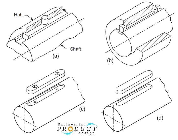
Fatigue stress concentration factor \[K_ft\]for keyways as shown in the figure below for the common keyway types of Sled-runner (a) and Profile keyway or end milled (b).
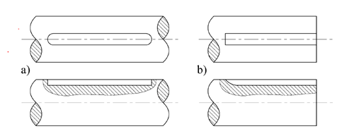
- Sled-runner – 1.44
- Profile keyway or end milled – 1.68
Shaft Key failure
The potential keyed joint failure include yielding, ductile rupture, fatigue and fretting fatigue of the key or the shaft keyway. It is often advantageous to size the keyed joint so that it will scarify itself and shear off by ductile rupture in the event of torque overload. Using the key as an inexpensive fuse to safeguard expensive machine elements.
Key sizing
There are two types of forces that act on the key due to installation and power transmission. The compressive force (f1) induced by the tight-fitting of the key is very difficult to determine and if the correct tolerances are used as per the standards, then this will be comparably less.
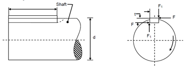
Force F is induced on the side of the key as shown due to the torque transmitted and producing both shearing and compressive stresses. Resulting in the following two types of failure mechanics.
- Shear failure
- Compressive bearing forces
The compressive bearing stress on the contact plane
\[S_c= 4T/dhl\]
Average shearing stress across the shearing plane is calculated
\[ τ_s= 2T/dwl \]
Where
| \[T\] | Torque |
| \[d \] | shaft diameter |
| \[w\] | key width |
| \[l\] | Key length |
| \[τ_s\] | Average shear stress |
| \[S_c\] | Compressive bearing stress |
The required key length can be obtained using either the maximum shear stress theory or by setting the average stress equal to the allowable shear stress.
The design permissible torque can be calculated from the above equation.
\[ T_k \] = \[τ_sdwl/2\]
Where \[τ_s\] is designed permissible shearing stress for the applicable failure mode. From shaft design, the design allowed torque can be found using the following formula
\[T_s = πd^3 τ_d/16 K_f\]
If the key is selected to have the same design allowable stress as the shaft then the length of the key can be found using the following formula
\[ T_k = T_s \]
\[ Le = π d^2 / 8wK_f\]
Where
| \[T_k\] | Permissible torque for key |
| \[T_s \] | Permissible torque for shaft |
| \[L_e\] | Effective key length |
| \[K_f \] | Fatigue stress concentration factor |
Keys & keyways specification
Standards & Specification
Refer to tabulated dimensions and tolerances of metric keyways for parallel and woodruff keys as per BS 4235-1:1972. Along with keyway size tolerances and keyway depth sizes, some standards also provide information on the recommended key size and keyway depth as a function of shaft diameter.
- Recommendations for key size, length and keyway depth as a function of shaft diameter are provided in ASME Standards B17.1-1967, ASME standard B17.2-1967.
- Specification for metric keys and keyways – Parallel and taper keys BS 4235-1:1972
- Matching the woodruff key to the shaft diameter is also specified in DIN 6888
- Tangential Keys and Tangential Keyways for alternating shock loads specification DIN 268:1974
- Tangential Keys and Tangential Keyways for constant loads specification DIN 271:1974
Dimensions and tolerances of metric keyways for parallel keys
Keys and keyways secure the hub and shaft to prevent relative movement between a power transmitting shaft and an attached component.
Read more on how keys and keyways work and what types are available – Keys and Keyways
For example, Gear drives, Pulleys or Sprockets are connected securely using keys to the power transmitting shaft.
1972)
| Shaft | Key | Key way | |||||||||||||||||
|---|---|---|---|---|---|---|---|---|---|---|---|---|---|---|---|---|---|---|---|
| Nominal Diameter | Size | Width ( b ) | Depth (t) | Radius ( r ) | |||||||||||||||
| Nom | Free | Normal | Close/ Interference | Shaft (t1) | Hub (t2) | ||||||||||||||
| d | Shaft (H9) | Hub (D10) | Shaft (N9) | Hub (Js9) | Shaft/Hub (P9) | ||||||||||||||
| Over | Incl | b x h | Min | Max | Min | Max | Min | Max | Min | Max | Min | Max | Min | Max | Min | Max | Min | Max | |
| 6 | 8 | 2×2 | 2 | 0 | +0,025 | +0,02 | +0,06 | -0,029 | -0,004 | -0,012 | +0,012 | -0,031 | -0,006 | 1,2 | 1.3 | 1,0 | 1.1 | 0,08 | 0,16 |
| 8 | 10 | 3×3 | 3 | 0 | +0,025 | +0,02 | +0,06 | -0,029 | -0,004 | -0,012 | +0,012 | -0,031 | -0,006 | 1,8 | 1.9 | 1,4 | 1.5 | 0,08 | 0,16 |
| 10 | 12 | 4×4 | 4 | 0 | +0,03 | +0,030 | +0,078 | -0,030 | 0 | -0,015 | +0,015 | -0,042 | -0,012 | 2,5 | 2.6 | 1,8 | 1.9 | 0,08 | 0,16 |
| 12 | 17 | 5×5 | 5 | 0 | +0,03 | +0,030 | +0,078 | -0,030 | 0 | -0,015 | +0,015 | -0,042 | -0,012 | 3,0 | 3.1 | 2,3 | 2.4 | 0,16 | 0,25 |
| 17 | 22 | 6×6 | 6 | 0 | +0,03 | +0,030 | +0,078 | -0,030 | 0 | -0,015 | +0,015 | -0,042 | -0,012 | 3,5 | 3.6 | 2,8 | 2.9 | 0,16 | 0,25 |
| 22 | 30 | 8×7 | 8 | 0 | +0,036 | +0,040 | +0,098 | -0,036 | 0 | -0,018 | +0,018 | -0,051 | -0,015 | 4,0 | 4.2 | 3,3 | 3,5 | 0,16 | 0,25 |
| 30 | 38 | 10×8 | 10 | 0 | +0,036 | +0,040 | +0,098 | -0,036 | 0 | -0,018 | +0,018 | -0,051 | -0,015 | 5,0 | 5.2 | 3,3 | 3,5 | 0,25 | 0,40 |
| 38 | 44 | 12×8 | 12 | 0 | +0,043 | +0,050 | +0,12 | -0,043 | 0 | -0,021 | +0,021 | -0,061 | -0,018 | 5,0 | 5.2 | 3,3 | 3,5 | 0,25 | 0,40 |
| 44 | 50 | 14×9 | 14 | 0 | +0,043 | +0,050 | +0,12 | -0,043 | 0 | -0,021 | +0,021 | -0,061 | -0,018 | 5,5 | 5.7 | 3,8 | 4,0 | 0,25 | 0,40 |
| 50 | 58 | 16×10 | 16 | 0 | +0,043 | +0,050 | +0,12 | -0,043 | 0 | -0,021 | +0,021 | -0,061 | -0,018 | 6,0 | 6.2 | 4,3 | 4,5 | 0,25 | 0,40 |
| 58 | 65 | 18×11 | 18 | 0 | +0,043 | +0,050 | +0,12 | -0,043 | 0 | -0,021 | +0,021 | -0,061 | -0,018 | 7,0 | 7.2 | 4,4 | 4,6 | 0,25 | 0,40 |
| 65 | 75 | 20×12 | 20 | 0 | +0,052 | +0,065 | +0,149 | -0,052 | 0 | -0,026 | +0,026 | -0,074 | -0,022 | 7,5 | 7.7 | 4,9 | 5,1 | 0,40 | 0,60 |
| 75 | 85 | 22×14 | 22 | 0 | +0,052 | +0,065 | +0,149 | -0,052 | 0 | -0,026 | +0,026 | -0,074 | -0,022 | 9,0 | 9.2 | 5,4 | 5,6 | 0,40 | 0,60 |
| 85 | 95 | 25×14 | 25 | 0 | +0,052 | +0,065 | +0,149 | -0,052 | 0 | -0,026 | +0,026 | -0,074 | -0,022 | 9,0 | 9.2 | 5,4 | 5,6 | 0,40 | 0,60 |
| 95 | 110 | 28×16 | 28 | 0 | +0,052 | +0,065 | +0,149 | -0,052 | 0 | -0,026 | +0,026 | -0,074 | -0,022 | 10,0 | 10.2 | 6,4 | 6,6 | 0,40 | 0,60 |
| 110 | 130 | 32×18 | 32 | 0 | +0,062 | +0,080 | +0,18 | -0,062 | 0 | -0,031 | +0,031 | -0,088 | -0,026 | 11,0 | 11.2 | 7,4 | 7,6 | 0,4 | 0,6 |
| 130 | 150 | 36×20 | 36 | 0 | +0,062 | +0,080 | +0,18 | -0,062 | 0 | -0,031 | +0,031 | -0,088 | -0,026 | 12,0 | 12.3 | 8,4 | 8.7 | 0,7 | 1,0 |
| 150 | 170 | 40×22 | 40 | 0 | +0,062 | +0,080 | +0,18 | -0,062 | 0 | -0,031 | +0,031 | -0,088 | -0,026 | 13,0 | 13.3 | 9,4 | 9.7 | 0,7 | 1,0 |
| 170 | 200 | 45×25 | 45 | 0 | +0,062 | +0,080 | +0,18 | -0,062 | 0 | -0,031 | +0,031 | -0,088 | -0,026 | 15,0 | 15.3 | 10,4 | 10.7 | 0,7 | 1,0 |
| 200 | 230 | 50×28 | 50 | 0 | +0,062 | +0,080 | +0,18 | -0,062 | 0 | -0,031 | +0,031 | -0,088 | -0,026 | 17,0 | 17.3 | 11,4 | 11.7 | 0,7 | 1,0 |
| 230 | 260 | 56×32 | 56 | 0 | +0,074 | 0,100 | +0,220 | -0,074 | 0 | -0,037 | +0,037 | -0,106 | -0,032 | 20,0 | 20.3 | 12,4 | 12.7 | 1,2 | 1,6 |
| 260 | 290 | 63×32 | 63 | 0 | +0,074 | 0,100 | +0,220 | -0,074 | 0 | -0,037 | +0,037 | -0,106 | -0,032 | 20,0 | 20.3 | 12,4 | 12.7 | 1,2 | 1,6 |
| 290 | 330 | 70×36 | 70 | 0 | +0,074 | 0,100 | +0,220 | -0,074 | 0 | -0,037 | +0,037 | -0,106 | -0,032 | 22,0 | 22.3 | 14,4 | 14.7 | 1,2 | 1,6 |
| 330 | 380 | 80×40 | 80 | 0 | +0,074 | 0,100 | +0,220 | -0,074 | 0 | -0,037 | +0,037 | -0,106 | -0,032 | 25,0 | 25.3 | 15,4 | 15.7 | 2,0 | 2,5 |
| 380 | 440 | 90×45 | 90 | 0 | +0,087 | 0,120 | +0,260 | -0,087 | 0 | -0,043 | +0,043 | -0,124 | -0,037 | 28,0 | 28.3 | 17,4 | 17.7 | 2,0 | 2,5 |
| 440 | 500 | 100×50 | 100 | 0 | +0,087 | 0,120 | +0,260 | -0,087 | 0 | -0,043 | +0,043 | -0,124 | -0,037 | 31,0 | 31.3 | 19.5 | 19.8 | 2,0 | 2,5 |
Table 01.Dimensions and tolerances of keyways for parallel keys (source: BS 4235-1:1972)
Woodruff keys specification
| Key | Key way | ||||||||||||
|---|---|---|---|---|---|---|---|---|---|---|---|---|---|
| Size | Width ( b ) | Depth (t) | Radius ( r ) | ||||||||||
| Nom | Normal | Close/ Interference | Shaft (t1) | Hub (t2) | |||||||||
| Shaft (N9) | Hub (Js9) | Shaft/Hub (P6) | |||||||||||
| b x h1 x D | Min | Max | Min | Max | Min | Max | Min | Max | Min | Max | Min | Max | |
| 1,0 x 1,4 x 4 | 1 | -0,029 | -0,004 | -0,012 | +0,012 | -0,0031 | -0,006 | 1,0 | 1,1 | 0,6 | 0,7 | 0,16 | 0,08 |
| 1,5 x 2,6 x 7 | 1,5 | -0,029 | -0,004 | -0,012 | +0,012 | -0,0031 | -0,006 | 2,0 | 2,1 | 0,8 | 0,9 | 0,16 | 0,08 |
| 2,0 x 2,6 x 7 | 2,0 | -0,029 | -0,004 | -0,012 | +0,012 | -0,0031 | -0,006 | 1,8 | 1,9 | 1,0 | 1,1 | 0,16 | 0,08 |
| 2,0 x 3,7 x 10 | 2,0 | -0,029 | -0,004 | -0,012 | +0,012 | -0,0031 | -0,006 | 2,9 | 3,0 | 1,0 | 1,1 | 0,16 | 0,08 |
| 2,5 x 3,7 x 10 | 2,5 | -0,029 | -0,004 | -0,012 | +0,012 | -0,0031 | -0,006 | 2,7 | 2,8 | 1,2 | 1,3 | 0,16 | 0,08 |
| 3,0 x 5,0 x 13 | 3,0 | -0,029 | -0,004 | -0,012 | +0,012 | -0,0031 | -0,006 | 3,8 | 4,0 | 1,4 | 1,5 | 0,16 | 0,08 |
| 3,0 x 6,5 x 16 | 3,0 | -0,029 | -0,004 | -0,012 | +0,012 | -0,0031 | -0,006 | 5,3 | 5,5 | 1,4 | 1,5 | 0,16 | 0,08 |
| 4,0 x 6,5 x 16 | 4,0 | -0,030 | 0 | -0,015 | +0,015 | -0,042 | -0,012 | 5,0 | 5,2 | 1,8 | 1,9 | 0,25 | 0,16 |
| 4,0 x 7,5 x 19 | 4,0 | -0,030 | 0 | -0,015 | +0,015 | -0,042 | -0,012 | 6,0 | 6,2 | 1,8 | 1,9 | 0,25 | 0,16 |
| 5,0 x 6,5 x 16 | 5,0 | -0,030 | 0 | -0,015 | +0,015 | -0,042 | -0,012 | 4,5 | 4,7 | 2,3 | 2,4 | 0,25 | 0,16 |
| 5,0 x 7,5 x 19 | 5,0 | -0,030 | 0 | -0,015 | +0,015 | -0,042 | -0,012 | 5,5 | 5,7 | 2,3 | 2,4 | 0,25 | 0,16 |
| 5,0 x 9.0 x 22 | 5,0 | -0,030 | 0 | -0,015 | +0,015 | -0,042 | -0,012 | 7,0 | 7,3 | 2,3 | 2,4 | 0,25 | 0,16 |
| 6,0 x 9,0 x 22 | 6,0 | -0,030 | 0 | -0,015 | +0,015 | -0,042 | -0,012 | 6,5 | 6,8 | 2,8 | 2,9 | 0,25 | 0,16 |
| 6,0 x 11,0 x 28 | 6,0 | -0,030 | 0 | -0,015 | +0,015 | -0,042 | -0,012 | 7,5 | 7,8 | 2,8 | 3,0 | 0,25 | 0,16 |
| 8,0 x 11,0 x 28 | 8,0 | -0.036 | 0 | -0.018 | +0,018 | -0.051 | +0,015 | 8,0 | 8,3 | 3,3 | 3,5 | 0,40 | 0,25 |
| 10,0×13,0x32 | 10,0 | -0.036 | 0 | -0.018 | +0,018 | -0.051 | +0,015 | 10,0 | 10,3 | 3,3 | 3,5 | 0,4 | 0,25 |
Table 02.Dimensions and tolerances of metric keyways for Woodruff keys
References
- Collins, J. A., Busby, H., & Staab, G. (n.d.). Mechanical Design of Machine Elements and Machines.John Wiley & Sons.
- Hamrock, B. J., Schmid, S. R., & Jacobson, B. O. (2006). Fundamentals of machine elements: Bernard J. Hamrock, Steven R. Schmid, Bo O. Jacobson. Boston: McGraw-Hill Higher Education.
- Kurt M. Marshek, Robert C. Juvinall (2021). Fundamentals of machine component design. John Wiley & Sons.