Shaft splines & serrations are used to transmit rotational torque on the same axis and connect mechanical elements such as gears and pulleys.
Contents covered in this article
What are splines and serrations?
shaft splines and serrations are ridges, or teeth-type keys, that are an integral part of the shaft that mesh with grooves in a mating hub to transfer torque and rotational motion. For example, a bevel gear mounted on a shaft might use a male shaft spline that matches the female spline on the gear, as shown below.
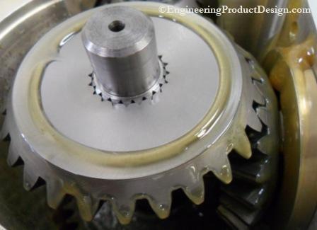
Although a splined shaft looks like having a series of shaft keyways with keys pushed in, splines are considerably stronger than the keyed joint as the keyways weaken the shaft and reduce its torque-carrying capacity.
Application of splines and serrations
Although they look like gears, Splines only transmit torque and rotation on the same axis. They are used mainly for the following reasons.
- Mechanical transmission elements such as gears and pulleys might need to be removed from the shaft due to design for manufacture and assembly (DFMA), ie during assembly or to aid manufacturing.
- Relative axial movement of the mechanical transmission element is required for functional purposes such as speed reducers and clutches.
- High torque transfer is required.
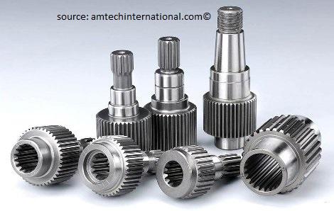
A good spline joint provides very high secure torque transmission, little clearance, minimum backlash, good centring between the coupled components, low noise, low wear and small or no axial forces.
Surface wear, fretting corrosion, tooth breakage and fatigue failure are the most common failure modes associated with spline joints.
Types of Splines and Serrations
The term “spline” provides an umbrella term for all profiles, and the splines can be divided into the following three groups based on their flank form.
- Parallel-sided or straight-sided spline
- Involute spline
- Serration
Depending on their relative axial movement, splines and serrations can also be grouped as fixed splines or flexible splines. As the name suggests, a fixed spline is a joint that does not move axially, such as gears, pullers, turbine wheels, etc.
Flexible splines slide axially, mainly used between shafts couplings and do not carry much torque as fixed spline joints.
Parallel-sided or Straight-sided spline
These have straight and parallel tooth flanks, as shown in the figure below, and as per various standards, number of teeth can vary from 4 to 12. They can transmit higher torque than involute splines and serrations because of their large tooth thickness from the minor to the major diameter of the profile. But might fail due to fatigue due to stress concentration in the root of the flanks.
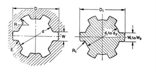
Naturally, it lacks centring ability because of the straight flanks, forcing it to rely on the major and minor diameter fits to manage the centring. Because of the straight-sided face, there will be a line of contact and surface contact will only exist after some wear.
Involute
Involute splines are very common and similar to internal and external involute gear teeth. They are comparably stronger than the parallel spline because of the lower stress concentration factor and have better surface quality. Involute splines can be produced by gear manufacturing techniques and have the ability to self-centre under load.
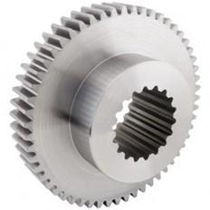
Involute splines are made with pressure angles 30o, 37.5 and 45o and can include between 60 and 100 splines per the American National Standard. Involute splines can be either Side fit or Diameter fit.
Serrations
Serrations also have straight flanks but are angled, as shown in the figure below. The biggest advantage of the serrations is that the angles flanks centre the shafts and the hub resulting in self-centring splines. Flank angles are generally between 50o and 90o.
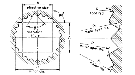
The main disadvantages of serrations are due to comparably small teeth, it can only be used for low torque applications. These are only used for non-axial moving applications. Like straight-sided splines, there will be line contact and wear.
Spline strength calculation
During the design of shaft splines and serrations, the following stresses must be considered to evaluate the suitability of the spline joint strength.
- Spline shaft shear stress
- Spline teeth shear stress
- Spline teeth compressive stress
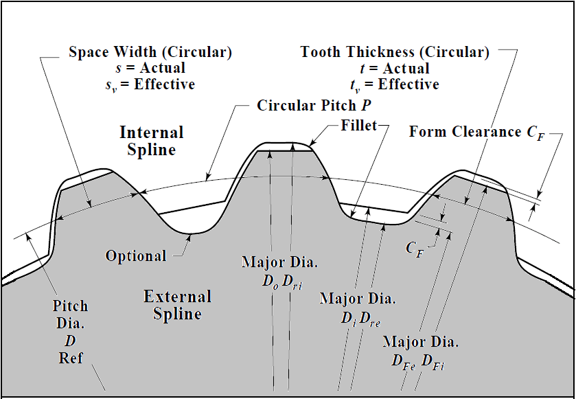
Generally, the shaft diameter is dictated by the overall design, such as bearing arrangements, seals, elements etc. In that instance, the spline strength calculations can be used in two ways.
- Stress calculation can be used to find the safety factor by calculating the stress involved and comparing it with the allowable stresses as per failure modes.
- Using the safety factor, the spline connection can be defined using spline length, spline type, number of splines etc.
Spline shaft shear stress
| Solid shaft stresses | Hollow shaft stresses |
|---|---|
| \[ S_s = \frac{16T}{\pi{D_{re}}^{3}} \] | \[ S_s = \frac{16T{D_{re}}}{\pi ({D_{re}}^4-D_h^4)} \] |
| Where | |
| \[S_s\] | Shear stress |
| \[{D_{re}}\] | Diameter of the spline |
| \[T\] | Torque |
| \[{D_{h}}\] | Bore diameter of hollow shaft |
Calculated stress using the above equations must not exceed the allowable stress (\[S^a\]) of the spline material and can be shown as follows
\[S^a_s \geq S_s \frac{{K_{a}}}{{L_{f}}}\]Usually, the safety factor is calculated using the allowable stress for various materials using the following equations.
| Allowable shaft stress | |
|---|---|
| \[S^a_s = {N_{sf}}S_s \frac{{K_{a}}}{{L_{f}}}\] | \[S^a_s \geq S_s \frac{{K_{a}}}{{L_{f}}}\] |
| Where | |
| \[S_s\] | Shear stress |
| \[S^a_{s}\] | Allowable shear stress |
| \[T\] | Torque |
| \[{L_{f}}\] | Life factor |
| \[{N_{sf}}\] | Safety factor |
| \[{K_{a}}\] | Application factor |
Spline teeth shear stress
| Shear stress in spline teeth | |
|---|---|
| \[S_s = \frac{4T{K_{m}}}{DN{F_{e}}{t_{e}}}\] | |
| \[S_s\] | Induced shear stress in spines |
| \[D\] | Pitch diameter |
| \[T\] | Torque |
| \[{K_{m}}\] | Load distribution factor |
| \[{F_{e}}\] | Effective face width |
| \[{t_{e}}\] | Chordal thickness at pitch line ( approximately equal to D/2N) |
| \[N\] | Number of spline teeth |
Spline teeth compressive stress
| Compressive stress on spline teeth | |
|---|---|
| \[ S_c = \frac{2T{K_{m}}}{DN{F_{e}h}} \] | |
| \[S_c\] | Compressive stress |
| \[{K_{m}}\] | Load distribution factor |
| \[T\] | Torque |
| \[{F_{e}}\] | Effective face width |
| \[h\] | Radial height of the tooth in contact |
Again similar to shear stresses, calculated compressive stresses should be compared with allowable compressive stress and must not exceed them to avoid failure.
\[S^a_s \geq S_s \frac{{K_{a}}}{{L_{f}}}\] – Flexible splines\[S^a_s \geq S_s \frac{{K_{a}}}{{L_{f}}}\] – Fixed splines| Allowable shaft stress | |
|---|---|
| Flexible splines | Fixed Splines |
| \[S^a_c = {N_{sf}}S_c \frac{{K_{a}}}{{L_{w}}}\] | \[S^a_c = {N_{sf}}S_c \frac{{K_{a}}}{{9L_{f}}}\] |
| Where | |
| \[S_s\] | Shear stress |
| \[{S^a_{s}}\] | Allowable shear stress |
| \[T\] | Torque |
| \[{L_{f}}\] | Life factor |
| \[{N_{sf}}\] | Safety factor |
| \[{K_{a}}\] | Application factor |
Spline stress factors
Allowable stress
The relationship between allowable stress and specified minimum yield strength as per the AISC code.
| Allowable stresses vs Yield strength | |
|---|---|
| Allowable tensile stress | \[{0.45}S_{y}\leq S^a_{t}\leq {0.6}S_{y}\] |
| Allowable Shear stress (\[{S^a_{s}}\]) | \[S^a_{s}= 0.4S_{y }\] |
| Allowable compressive/bearing stress (\[{S^a_{c}}\]) | \[0.45S_{y}\leq S^a_{c} \leq 0.6S_{y}\] |
| Allowable bending stress (\[{S^a{b}}\]) | \[0.6S_{y} \leq S^a_{b} \leq 0.75S_{y} \] |
| Where | |
| \[{S_{y}}\] | Material yield strength |
Load distribution factor for splines Km
The load is equally distributed if the transferring load is purely radial torsion and the torsional radial load is in the middle of the spline length. But if, for example, a bevel gear is used, this will put some unwanted axial loads into the spline.
Misalignment of spline couplings has been recognized as harmful to splines because it causes significant load concentration on spline teeth and accelerates spline wear and fretting fatigue.
| Load distribution factor for splines Km | ||||
|---|---|---|---|---|
| Effective face width (Fe) | ||||
| Misalignment | ½-in. (12.7 mm) | 1-in. (25.4 mm) | 2-in. (50.8 mm) | 4-in. (101.6) |
| 0.001 in. / in. (mm/mm) | 1 | 1 | 1 | 1 ½ |
| 0.002 in. / in. (mm/mm) | 1 | 1 | 1 ½ | 2 |
| 0.004 in. / in. (mm/mm) | 1 | 1 ½ | 2 | 2 ½ |
| 0.008 in. / in. (mm/mm) | 1 ½ | 2 | 2 ½ | 3 |
The following two papers discuss the load distribution factor and how it can affect the life of the spline joint.
- https://www.geartechnology.com/issues/0514x/spline-joints.pdf
- https://www.powertransmission.com/issues/0214/spline-couplings.pdf
Fatigue life factor for splines- Lf
| Number of torque cycles | Fatugue Life Factor, Lf | |
|---|---|---|
| Unidirectional | Fully – reversed | |
| 1,000 | 1.8 | 1.8 |
| 10,000 | 1.0 | 1.0 |
| 100,000 | 0.5 | 0.4 |
| 1,000,000 | 0.4 | 0.3 |
| 10,000,000 | 0.3 | 0.2 |
Spline application factor – Ka
If there are any axial or radial shock loading on the element connected, then care should be taken to support the external axial and radial shock loads to increase the joint life. This should also be considered during the calculations using the spline application factor.
The application factor compensates for any uncertainties in loads and impacts, where if everything is smooth and uniform then Ka is equal to 1.
| Input source category (Driving input or machine) | Type of Load | |||
|---|---|---|---|---|
| Uniform | Light shock | Intermittent Shock | heavy shock | |
| Generators, Fans | Oscillating pumps | Actuators | Presses, Shears | |
| Uniform (Turbine, Motor) | 1 | 1.2 | 1.5 | 1.8 |
| light shock, (Hydraulic Motor) | 1.2 | 1.3 | 1.8 | 2.1 |
| Medium shock, (Internal combustion engine | 2 | 2.2 | 2.4 | 2.8 |
Table 1 Spline application Factor (Ka)
Wear life factor for splines Lw
Life factors for splines under wear conditions are based on the number of revolutions of the spline joint, not reversible cycles. Wear life factor only applies to flexible or sliding spline compressive stress calculations, as each time the spline slide back and forth, it wears the teeth.
| No of revolutions of the spline | Wear life factor for splines (Lw ) |
|---|---|
| 10,000 | 4 |
| 100,000 | 2.8 |
| 1,000,000 | 2 |
| 10,000,000 | 1.4 |
| 100,000,000 | 1 |
| 1,000,000,000 | 0.7 |
| 10,000,000,000 | 0.5 |
#Productdesigntip Fixed spline can carry 9 times more compressive stresses than flexible spline
Standards
- Society of Automotive Engineering standard parallel side splines SAE J 499-2014
- The American standard for involute and straight-sided spline profile ANSI B92.1
- IS 2610 – power transmission-straight sided splines for machine tools dimensions.
- IS 3665 – Dimensions for involute-sided splines
- IS 2327 – Straight-sided splines for cylindrical shafts
- BS 2059 Straight-sided splines and serrations
- DIN 5463 – spline shaft connections with straight flanks; medium series
- DIN 5480 – Involute splines based on reference diameters
- Some other standards – DIN 5480, DIN 5481, DIN 5482, ISO 4156, E22-141, E22-145, ANSI and SAE standards
References and recommended reading
- Dudley, D. W. (n.d.). When splines need stress control.
- Oberg, E., Jones, F. D., Horton, H. L., & Ryffel, H. H. (2016). Machinery’s handbook.
- Lingaiah, K. (2007). Machine design databook. (Lingaiah, K.: Machine design databook.) Norwich, NY: Knovel.
- Bhandari, V. B. (2017). Design of machine elements. New Delhi: McGraw-Hill Education (India).
- British Standards Institution. 2059 (1953). Straight-sided splines and serrations. London: B.S.I.